FLYWHEEL
DESCRIPTION
STANDARD FLYWHEEL
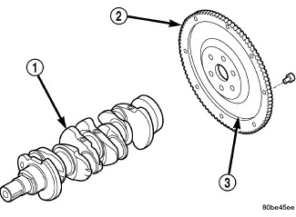 |
The standard flywheel (3) is a heavy plate bolted to the rear of the crankshaft (1). The flywheel incorporates the ring gear (2) to mesh with the starter. The rear face of the flywheel serves as the driving member to the clutch disc.
DUAL MASS FLYWHEEL
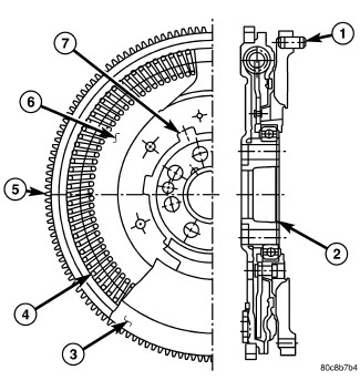 |
The Dual Mass Flywheel incorporates the ring gear to mesh with the starter. The primary flywheel (6) side is bolted to the crankshaft. The secondary flywheel (3) face serves as the driving member to the clutch disc. Internal springs (4) between the flywheels are use to dampen energy.
OPERATION
The flywheel serves to dampen the engine firing pulses. The heavy weight of the flywheel relative to the rotating mass of the engine components serves to stabilize the flow of power to the remainder of the drivetrain. The crankshaft has the tendency to attempt to speed up and slow down in response to the cylinder firing pulses. The flywheel dampens these impulses by absorbing energy when the crankshaft speeds and releasing the energy back into the system when the crankshaft slows down.
On a Dual Mass Flywheel the additional secondary mass coupled to the transmission lowers the natural frequency of the transmission rotating elements. This decreases the transmission gear rattle. The damper springs between the two flywheel masses replace the clutch disc damper springs and assist in a smooth transfer of torque to the transmission.
The Dual Mass Flywheel is serviced
as an assembly only and should never be taken apart. Failure to heed
caution may result in damage.
CAUTION:
DIAGNOSIS AND TESTING - FLYWHEEL
Check flywheel runout whenever misalignment is suspected. Flywheel runout should not exceed 0.08 mm (0.003 in.). Measure runout at the outer edge of the flywheel face with a dial indicator. Mount the indicator on a stud installed in place of one of the flywheel bolts.
Common causes of runout are:
- heat warpage
- improper machining
- incorrect bolt tightening
- improper seating on crankshaft flange shoulder
- foreign material on crankshaft flange
Flywheel machining is not recommended. The flywheel clutch surface is machined to a unique contour and machining will negate this feature. Minor flywheel scoring can be cleaned up by hand with 180 grit emery or with surface grinding equipment. Remove only enough material to reduce scoring (approximately 0.001 - 0.003 in.). Heavy stock removal is not recommended. Replace the flywheel if scoring is severe and deeper than 0.076 mm (0.003 in.). Excessive stock removal can result in flywheel cracking or warpage after installation; it can also weaken the flywheel and interfere with proper clutch release.
Clean the crankshaft flange before mounting the flywheel. Dirt and grease on the flange surface may cock the flywheel causing excessive runout. Use new bolts when remounting a flywheel and secure the bolts with Mopar Lock And Seal or equivalent. Tighten flywheel bolts to specified torque only. Overtightening can distort the flywheel hub causing runout.
REMOVAL
INSTALLATION
-
Clean the surfaces of the flywheel and pressure plate.
NOTE: When installing tone wheel, be sure the XXXXXXX printing on the tone wheel is facing outward
- If vehicle is equipted with start-stop feature, install tone wheel on crankshaft.
- On Diesel engine, Install flywheel with new bolts and tighten in a criss-cross pattern. Tighten bolts to 50 N·m (37 ft. lbs.).
-
Using a torque wrench fitted with a Torque Angle Gauge, (Goniometer), loosen one flywheel bolt at a time and tighten to 25 N·m (19 ft. lbs.) plus angle in relation to bolt length.
Bolt Length
Torque Angle
40 mm
60°
50 mm
75°
60 mm
90°
- On Gas engine, Install flywheel with new bolts and tighten in a criss-cross pattern. Tighten bolts to 90 N·m (67 ft. lbs.).
- Install clutch disc and pressure plate.
- Install transmission.