Lubrication
DESCRIPTION
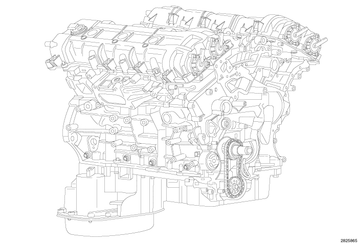 |
The lubrication system is a full flow filtration, pressure feed type lubrication system. The oil pump is mounted to the bottom of the cylinder block and chain driven by the crankshaft sprocket. The oil pump pick-up tube is attached to the oil pump and supported at the windage tray. There are three oil gallery plugs installed in the engine block. A system oil pressure sensor allows oil pressure to be monitored with a diagnostic scan tool. The oil pressure and oil temperature sensors are located on the oil filter housing assembly which is mounted to the top of the engine block between the cylinder heads. The oil cooler is mounted to the oil filter housing. There is a pressure relief valve in the oil pump that is only activated on a cold start or for emergency relief since the oil pump output is self-regulating. There are three piston oil cooler jets mounted to the engine block. Each jet cools two pistons.
OPERATION
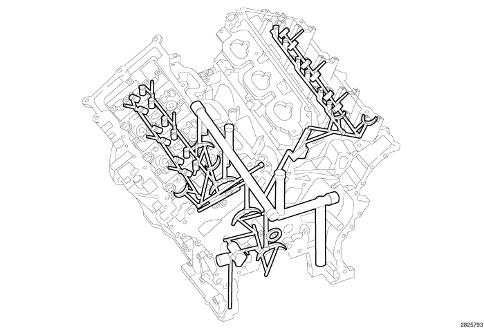 |
The oil from the oil pan is pumped by a vane type oil pump mounted to the bottom of the cylinder block that is chain driven by the crankshaft sprocket. The oil from the pump travels to the oil filter element and then to the oil cooler assembly. After the oil has been filtered and cooled, the oil enters the main oil gallery. The pressurized oil travels through the main gallery to the four main journals to lubricate the crankshaft main bearings. The pressurized oil travels through the crankshaft main journals to cross-drilling supplying oil to the connecting rod journals. From the number one main bearing gallery, oil travels to the right secondary chain tensioner and to the primary chain idler shaft. The main oil gallery also supplies oil to three sets of piston oil cooling jets. From the cylinder block the oil flows through drillings into the left and right cylinder heads. Left cylinder head oil is supplied to the left secondary timing chain tensioner, camshaft journals and hydraulic lash adjusters. Right cylinder hear oil is supplied to the right camshaft journals and hydraulic lash adjusters. The camshaft valve lobes and rocker arms are lubricated through a small hole in the rocker arm; oil flows through the lash adjuster then through the rocker arm and onto the camshaft lobe. Oil also flows through each of the four forward camshaft bearings into the camshafts and phasers.
Engine Lubrication Flow Chart
|
FROM |
TO |
|---|---|
|
Oil Pickup Tube |
Oil Pump |
|
Oil Pump |
Oil Filter |
|
Oil Filter |
Oil Cooler |
|
Oil Cooler |
Block Main Oil Gallery |
|
Block Main Oil Gallery |
1. Crankshaft Main Journals |
|
2. Left Cylinder Head |
|
|
3. Right Cylinder Head |
|
|
4. Piston Cooling Jets |
|
|
Crankshaft Number One Main Journal |
1. Primary Chain Idler Shaft |
|
2. Right Secondary Chain Tensioner |
|
|
3. Oil Pump Feedback |
|
|
Crankshaft Main Journals |
Crankshaft Rod Journals |
|
Left Cylinder Head |
1. Left Secondary Chain Tensioner |
|
2. Hydraulic Lash Adjusters |
|
|
3. Camshaft Journals |
|
|
4. Phaser Oil Control Valves |
|
|
Right Cylinder Head |
1. Hydraulic Lash Adjusters |
|
2. Camshaft Journals |
|
|
3. Phaser Oil Control Valves |
|
Hydraulic Lash Adjusters |
1. Rocker Arms |
|
2. Cam Lobes |
ENGINE OIL LEAK
Begin with a thorough visual inspection of the engine, particularly at the area of the suspected leak. If an oil leak source is not readily identifiable, the following steps should be followed:
- Do not clean or de-grease the engine at this time because some solvents may cause rubber to swell, temporarily stopping the leak.
- Add an oil soluble dye (use as recommended by manufacturer). Start the engine and let idle for approximately 15 minutes. Check the oil dipstick to make sure the dye is thoroughly mixed as indicated with a bright yellow color under a black light.
- Using a black light, inspect the entire engine for fluorescent dye, particularly at the suspected area of the oil leak. If the oil leak is found and identified, repair per service manual instructions.
- If dye is not observed, drive the vehicle at various speeds for approximately 24 km (15 miles), and repeat the inspection. If the oil leak source is not positively identified at this time, proceed with the air leak detection test method.
Air Leak Detection Test Method
- Disconnect the make-up air hose from the cylinder head cover. Cap or plug the make-up air hose nipple.
- Remove the PCV hose from the PCV valve. Cap or plug the PCV valve nipple.
-
Attach an air hose with a pressure gauge and regulator to the dipstick tube.
CAUTION: Do not subject the engine assembly to more than 20.6 kPa (3 PSI) of test pressure.
- Gradually increase air pressure from 1 psi to 2.5 psi maximum while applying soapy water at the suspected leak source. Adjust the regulator to a suitable test pressure within this range that provides the best bubble generation which will pinpoint the leak source. If the oil leak is detected and identified, repair per service manual procedures.
- If the leakage occurs at the rear oil seal area, follow the procedures for rear seal area leaks (Refer to 09 - Engine/Lubrication - Diagnosis and Testing) .
- If no leaks are detected, turn off the air supply and remove the air hose and all plugs and caps. Install the PCV valve and make-up air hoses.
- Clean the oil off of the suspect oil leak area using a suitable solvent. Drive the vehicle at various speeds approximately 24 km (15 miles). Inspect the engine for signs of an oil leak by using a black light.
CHECKING ENGINE OIL PRESSURE
 |
- Disconnect and isolate the negative battery cable.
-
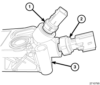
Remove the oil pressure sensor (2) from the oil filter housing (3) (Refer to 09 - Engine/Lubrication/SENSOR, Oil Pressure - Removal)
.
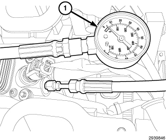
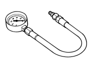
- Install Pressure Gauge C-3292A (1) to the oil pressure port. Tighten to 20 N·m (177 in. lbs.).
- Install the upper and lower intake manifolds and air inlet hose (Refer to 09 - Engine/Manifolds/MANIFOLD, Intake - Installation) .
- Connect the negative battery cable and tighten nut to 5 N·m (45 in. lbs.).
- Start and idle the engine. If oil pressure is 0 at idle, shut off the engine and consult the Engine Lubrication and Diagnostic Table (Refer to 09 - Engine - Diagnosis and Testing) .
- Run the engine until it reaches normal operating temperature.
-
Verify that the engine has acceptable oil pressure (Refer to 09 - Engine - Specifications)
REAR SEAL AREA LEAKS
 |
Since it is sometimes difficult to determine the source of an oil leak in the rear seal area of the engine, a more involved inspection is necessary. The following steps should be followed to help pinpoint the source of the leak.
If the leakage occurs at the crankshaft rear oil seal area:
- Disconnect and isolate the negative battery cable.
- Raise and support the vehicle (Refer to 04 - Vehicle Quick Reference/Hoisting - Standard Procedure) .
-
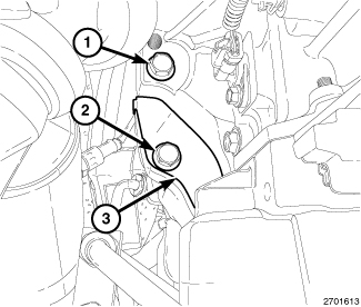
Remove the bolt (2) and the torque converter dust shield (3).
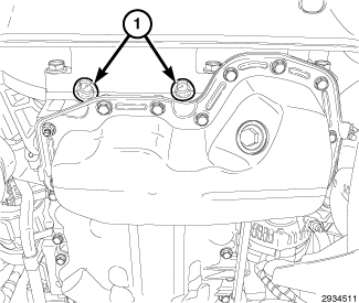
- Remove two rubber plugs (1) covering the rear oil seal retainer flange bolts.
- Inspect the flexplate and rear of the block for evidence of oil. Use a black light to check for the oil leak:
-
If no leaks are detected, use the Air Leak Detection Method as outlined in Engine Oil Leak (Refer to 09 - Engine/Lubrication - Diagnosis and Testing)
.
CAUTION: Do not subject the engine assembly to more than 20.6 kPa (3 PSI) of test pressure.
-
If the leak is not detected, very slowly turn the crankshaft and watch for leakage. If a leak is detected between the crankshaft and seal while slowly turning the crankshaft, it is possible the crankshaft seal surface is damaged. The seal area on the crankshaft could have minor nicks or scratches that can be polished out with emery cloth.
CAUTION: Use extreme caution when crankshaft polishing is necessary to remove minor nicks or scratches. The crankshaft seal flange is specially machined to complement the function of the rear oil seal.
-
For bubbles that remain steady with shaft rotation, no further inspection can be done until disassembled (Refer to 09 - Engine/Engine Block/SEAL, Crankshaft Oil - Removal)
.