AIR BAG, Seat
DESCRIPTION
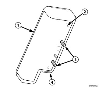 |
Seat AirBags (SAB) (also known as pelvic and thoracic airbags) are completely concealed beneath the seat back trim cover on the upper outboard sides of both front seat backs. Vehicles with this equipment can be readily identified by a sewn tag with the SRS - AIRBAG logo located on the outboard side of the front seat back trim cover. These airbags are inserted into a sewn pouch called an intensifier on the inside of the trim cover, then secured to the seat back frame by nuts on two studs (3). The two studs are located on the stamped metal SAB housing (2), while a metal locator tab between the two studs is integral to the stamped metal housing.
The folded SAB cushion is contained within a retainer wrap (1)
constructed of the same material as the airbag cushion. The inner
wrap cover completely encloses the airbag cushion and is engaged over
the studs on the housing for retention. The SAB cushion is constructed
of a coated nylon fabric. The SAB housing also contains the airbag
inflator and a heat shield.
The SAB inflator is a single-initiator, pyrotechnic-type unit that is secured to and sealed within the SAB housing. The SAB is connected to the vehicle electrical system through a dedicated jumper wire harness with a connector insulator that connects directly to the inflator initiator (4). The connector insulators are uniquely keyed and color-coded to ensure they can only be connected to the initiator.
The SAB cannot be repaired, and must be replaced if deployed, ineffective,
or in any way damaged. If the SAB is deployed, the seat back frame,
the seat back foam, the seat back trim cover and the airbag jumper
wire harness must also be replaced.
OPERATION
Each Seat AirBag (SAB) (also known as a pelvic and thoracic airbag) is deployed individually by an electrical signal generated by the Occupant Restraint Controller (ORC) to which it is connected through left or right SAB line 1 and line 2 (or squib) circuits. The hybrid-type inflator assembly for each SAB contains a small canister of highly compressed inert gas. When the ORC sends the proper electrical signal to the SAB inflator, the electrical energy creates enough heat to ignite chemical pellets within the inflator.
Once ignited, these chemicals burn rapidly and produce the pressure necessary to rupture a containment disk in the inert gas canister. The inflator and inert gas canister are sealed and connected so that all of the released gas is directed into the folded SAB cushion, causing the cushion to inflate. As the cushion inflates it will split the inner retainer wrap, the sewn pouch (intensifier) and the outboard side of the seat back trim cover and expand into the area between the outboard side of the front seat and the front door to form a cushion to protect the front seat occupant during a side impact collision.
Following the SAB deployment, the cushion slowly deflates by venting the inert gas through the loose weave of the cushion fabric, and the deflated cushion hangs down loosely from the outboard side of the front seat back.
The ORC monitors the condition of the SAB through circuit resistance, and will illuminate the airbag indicator in the instrument cluster and store a Diagnostic Trouble Code (DTC) for any fault that is detected. Proper diagnosis of the SAB inflator and squib circuits requires the use of a diagnostic scan tool and may also require the use of the SRS Load Tool special tool along with the appropriate Load Tool Jumpers and Adapters. Refer to the appropriate diagnostic information.
REMOVAL
To avoid serious or fatal injury
on vehicles equipped with airbags, disable the Supplemental Restraint
System (SRS) before attempting any steering wheel, steering column,
airbag, seat belt tensioner, impact sensor or instrument panel component
diagnosis or service. Disconnect and isolate the battery negative
(ground) cable, then wait two minutes for the system capacitor to
discharge before performing further diagnosis or service. This is
the only sure way to disable the SRS. Failure to take the proper precautions
could result in accidental airbag deployment.
WARNING:
To avoid serious or fatal injury
when removing a deployed airbag, rubber gloves, eye protection, and
a long-sleeved shirt should be worn. There may be deposits on the
airbag unit and other interior surfaces. In large doses, these deposits
may cause irritation to the skin and eyes.
WARNING:
 |
| NOTE: |
The following procedure is for replacement of an ineffective or damaged Seat AirBag (SAB). If the airbag is ineffective or damaged, but not deployed, review the recommended procedures for Handling Non-Deployed Supplemental Restraints. (Refer to 10 - Restraints - Standard Procedure) . If the SAB has been deployed, review the recommended procedures for Service After A Supplemental Restraint Deployment before removing the airbag from the vehicle. (Refer to 10 - Restraints - Standard Procedure) . |
- Position the front seat to its most forward position for easiest access to the front seat back.
- Disconnect and isolate the negative cable from the battery. Wait two minutes for the system capacitor to discharge before further service.
- Fold the seat back rearward for easiest access to the J-hook retainers at the base of the seat back trim cover.
- Disengage the J-hook retainers that secure the front and rear lower edges of the seat back trim cover to each other at the base of the seat back.
- Fold the seat back forward for easiest access to the back of the seat back trim cover.
- Remove the recliner handle and, on the passenger side only, the easy entry handle from the outboard side of the seat.
-
Pull up the front and
rear lower edges of the seat back trim cover far enough to access
the Seat AirBag (SAB) unit on the outboard side of the seat back frame.
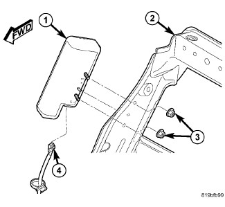
CAUTION: Do not pull on the seat airbag jumper wire harness (4) or pry on the connector insulator to disengage the connector from the seat airbag (1) inflator connector receptacle. Improper removal of this jumper wire and its connector insulator can result in damage to the airbag circuits or the connector insulator.
-
Reach between the seat
back trim cover and the foam pad on the outboard side of the seat
back frame to access and disconnect the SAB jumper wire harness connector
from the SAB inflator. Squeeze the black latch tabs on each side of
the connector insulator, then pull the insulator straight out from
the inflator initiator to disconnect it from the connector receptacle.
CAUTION: During removal of the seat airbag, be certain not to tear or damage the sewn nylon pouch integral to the inside of the seat back trim cover that contains the seat airbag. If the nylon pouch or the trim cover are torn or damaged, the entire front seat back trim cover must be replaced with a new unit.
- Remove the two nuts (3) from the inboard side of the outboard seat back frame that secure the SAB to the side of the seat back.
- Pull the SAB outward from the seat back far enough to disengage the airbag mounting studs from the seat back frame.
-
Disengage the SAB from
the sewn pouch (intensifier) on the inside of the seat back trim cover
and remove the airbag from the seat back.
INSTALLATION
To avoid serious or fatal injury
on vehicles equipped with airbags, disable the Supplemental Restraint
System (SRS) before attempting any steering wheel, steering column,
airbag, seat belt tensioner, impact sensor or instrument panel component
diagnosis or service. Disconnect and isolate the battery negative
(ground) cable, then wait two minutes for the system capacitor to
discharge before performing further diagnosis or service. This is
the only sure way to disable the SRS. Failure to take the proper precautions
could result in accidental airbag deployment.
WARNING:
|
| NOTE: |
The following procedure is for replacement of an ineffective or damaged Seat AirBag (SAB). If the airbag is ineffective or damaged, but not deployed, review the recommended procedures for Handling Non-Deployed Supplemental Restraints. (Refer to 10 - Restraints - Standard Procedure) . If the SAB has been deployed, review the recommended procedures for Service After A Supplemental Restraint Deployment before removing the airbag from the vehicle. (Refer to 10 - Restraints - Standard Procedure) . |
- Insert the Seat AirBag (SAB) (1) into the sewn nylon pouch (intensifier) on the inside of the outboard seat back trim cover.
- Position the SAB and pouch to the outboard side of the seat back frame (2) and insert the studs through the mounting holes in the frame.
- Install and tighten the two nuts (3) that secure the SAB to the side of the seat back frame. Tighten the nuts to 10 N·m (89 in. lbs.).
-
Reach between the seat
back trim cover and the foam pad on the outboard side of the seat
back frame to access and reconnect the SAB jumper wire harness (4)
connector to the SAB inflator. Be certain that the connector latches
are fully engaged.
CAUTION: Be certain that all of the trim is properly reinstalled on the front seat back frame. Failure to do so will adversely affect the function of the seat airbag system.
- Restore the front and rear lower edges of the seat back trim cover to the base of the seat back frame.
- Reinstall the recliner handle and, on the passenger side only, the easy entry handle to the outboard side of the seat.
- Fold the seat back rearward for easiest access to the J-hook retainers at the base of the seat back trim cover.
- Engage the J-hook retainers that secure the front and rear lower edges of the seat back trim cover to each other at the base of the seat back.
-
Do not reconnect the
negative cable to the battery at this time. The Supplemental Restraint
System (SRS) Verification Test procedure should be performed following
service of any SRS component. (Refer to 10 - Restraints - Standard Procedure)
.