SENSOR, Impact
FRONT
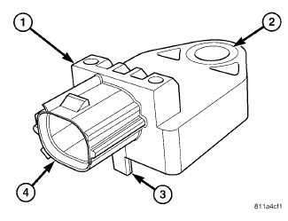 |
Two front impact sensors (1) are used on this vehicle, one each
for the left and right sides of the vehicle. These sensors are mounted
remotely from the impact sensor that is internal to the Occupant Restraint
Controller (ORC). Each front sensor is secured with a screw to the
back of the front end module carrier on either side of the cooling
module and inboard of the headlamp within the engine compartment.
The sensor housing has an integral connector receptacle (4), an integral
anti-rotation pin (3), and an integral mounting hole (2) with a metal
sleeve to provide crush protection.
The right and left front impact sensors are identical in construction and calibration. A cavity in the center of the molded black plastic impact sensor housing contains the electronic circuitry of the sensor which includes an electronic communication chip and an electronic impact sensor. A nylon cover is laser-welded over the cavity to seal and protect the internal electronic circuitry and components. The front impact sensors are each connected to the vehicle electrical system through a dedicated take out and connector of the front end module wire harness.
The impact sensors cannot be repaired or adjusted and, if damaged
or ineffective, they must be replaced.
SIDE
|
Two side impact sensors (1) are used with the optional seat airbags,
one each for the left and right sides of the vehicle. These sensors
are mounted remotely from the impact sensor that is internal to the
Occupant Restraint Controller (ORC). Each side sensor is secured with
a nut to a stud on the inner right or left B-pillar within the passenger
compartment. The sensor housing has an integral connector receptacle
(4), an integral anti-rotation pin (3), and an integral mounting hole
(2) with a metal sleeve to provide crush protection.
The right and left side impact sensors are identical in construction and calibration. A cavity in the center of the molded black plastic impact sensor housing contains the electronic circuitry of the sensor which includes an electronic communication chip and an electronic impact sensor. A nylon cover is laser-welded over the cavity to seal and protect the internal electronic circuitry and components. The side impact sensors are each connected to the vehicle electrical system through a dedicated take out and connector of the body wire harness.
The impact sensors cannot be repaired or adjusted and, if damaged
or ineffective, they must be replaced.
FRONT
The front impact sensors are electronic accelerometers that sense the rate of vehicle deceleration, which provides verification of the direction and severity of an impact. Each sensor also contains an electronic communication chip that allows the unit to communicate the sensor status as well as sensor fault information to the microcontroller within the Occupant Restraint Controller (ORC).
The ORC microcontroller continuously monitors all of the passive restraint system electrical circuits to determine the system readiness. If the ORC detects a monitored system fault, it sets a Diagnostic Trouble Code (DTC) and controls the airbag indicator operation accordingly. The impact sensors each receive battery current and ground through dedicated left and right sensor plus and minus circuits from the ORC. The impact sensors and the ORC communicate by modulating the voltage in the sensor plus circuit.
The hard wired circuits between the front impact sensors and the ORC may be diagnosed using conventional diagnostic tools and procedures. Refer to the appropriate wiring information. However, conventional diagnostic methods will not prove conclusive in the diagnosis of the impact sensors or the electronic controls and communication between other modules and devices that provide features of the supplemental restraint system. The most reliable, efficient and accurate means to diagnose the impact sensors or the electronic controls and communication related to front impact sensor operation requires the use of a diagnostic scan tool. Refer to the appropriate diagnostic information.
SIDE
The side impact sensors are electronic accelerometers that sense the rate of vehicle deceleration, which provides verification of the direction and severity of an impact. Each sensor also contains an electronic communication chip that allows the unit to communicate the sensor status as well as sensor fault information to the microcontroller within the Occupant Restraint Controller (ORC).
The ORC microcontroller continuously monitors all of the side passive restraint system electrical circuits to determine the system readiness. If the ORC detects a monitored system fault, it sets a Diagnostic Trouble Code (DTC) and controls the airbag indicator operation accordingly. The impact sensors each receive battery current and ground through the same left or right sensor plus and minus circuits in a series arrangement from the ORC. The impact sensors and the ORC communicate by modulating the voltage in the sensor plus circuit.
The hard wired circuits between the side impact sensors and the ORC may be diagnosed using conventional diagnostic tools and procedures. Refer to the appropriate wiring information. However, conventional diagnostic methods will not prove conclusive in the diagnosis of the impact sensors or the electronic controls and communication between other modules and devices that provide features of the supplemental restraint system. The most reliable, efficient and accurate means to diagnose the impact sensors or the electronic controls and communication related to side impact sensor operation requires the use of a diagnostic scan tool. Refer to the appropriate diagnostic information.
FRONT
To avoid serious or fatal injury
on vehicles equipped with airbags, disable the Supplemental Restraint
System (SRS) before attempting any steering wheel, steering column,
airbag, seat belt tensioner, impact sensor or instrument panel component
diagnosis or service. Disconnect and isolate the battery negative
(ground) cable, then wait two minutes for the system capacitor to
discharge before performing further diagnosis or service. This is
the only sure way to disable the SRS. Failure to take the proper precautions
could result in accidental airbag deployment.
WARNING:
To avoid serious or fatal injury,
never strike or drop the front impact sensor, as it can damage the
impact sensor or affect its calibration. The front impact sensor enables
the system to deploy the front supplemental restraints. If an impact
sensor is accidentally dropped during service, the sensor must be
scrapped and replaced with a new unit. Failure to observe this warning
could result in accidental, incomplete, or improper front supplemental
restraint deployment.
WARNING:
 |
| NOTE: |
The front and side impact sensors are interchangeable. |
- Disconnect and isolate the negative cable from the battery. Wait two minutes for the system capacitor to discharge before further service.
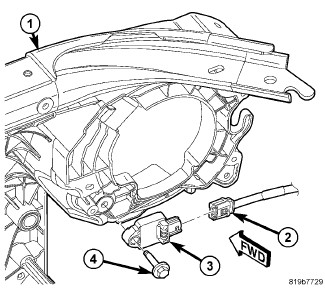
- Remove the screw (4) that secures the impact sensor (3) to the back (engine compartment side) of the front end module carrier (1) inboard of the right or left headlamp.
- Disconnect the engine compartment wire harness connector (2) from the right or left front impact sensor connector receptacle.
-
Remove the right or
left front impact sensor from the engine compartment.
SIDE - FOUR-DOOR
To avoid serious or fatal injury
on vehicles equipped with airbags, disable the Supplemental Restraint
System (SRS) before attempting any steering wheel, steering column,
airbag, seat belt tensioner, impact sensor or instrument panel component
diagnosis or service. Disconnect and isolate the battery negative
(ground) cable, then wait two minutes for the system capacitor to
discharge before performing further diagnosis or service. This is
the only sure way to disable the SRS. Failure to take the proper precautions
could result in accidental airbag deployment.
WARNING:
To avoid serious or fatal injury,
never strike or drop the side impact sensor, as it can damage the
impact sensor or affect its calibration. The side impact sensor enables
the system to deploy the side Supplemental Restraint System (SRS)
components. If an impact sensor is accidentally dropped during service,
the sensor must be scrapped and replaced with a new unit. Failure
to observe this warning could result in accidental, incomplete, or
improper side SRS component deployment.
WARNING:
 |
| NOTE: |
The front and side impact sensors are interchangeable. |
- Adjust the driver or passenger side front seat to its most forward position for easiest access to the B-pillar trim.
- Disconnect and isolate the negative cable from the battery. Wait two minutes for the system capacitor to discharge before further service.
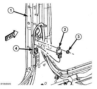
- Remove the trim from the inside of the lower right or left B-pillar (1). (Refer to 23 - Body/Interior/PANEL, B-Pillar Trim - Removal) .
- Remove the nut (3) that secures the side impact sensor (2) to the weld stud on the lower B-pillar.
- Remove the sensor from the weld stud on the inner B-pillar.
-
Disconnect the body
wire harness connector (4) from the sensor connector receptacle.
SIDE - TWO-DOOR
To avoid serious or fatal injury
on vehicles equipped with airbags, disable the Supplemental Restraint
System (SRS) before attempting any steering wheel, steering column,
airbag, seat belt tensioner, impact sensor or instrument panel component
diagnosis or service. Disconnect and isolate the battery negative
(ground) cable, then wait two minutes for the system capacitor to
discharge before performing further diagnosis or service. This is
the only sure way to disable the SRS. Failure to take the proper precautions
could result in accidental airbag deployment.
WARNING:
To avoid serious or fatal injury,
never strike or drop the side impact sensor, as it can damage the
impact sensor or affect its calibration. The side impact sensor enables
the system to deploy the side Supplemental Restraint System (SRS)
components. If an impact sensor is accidentally dropped during service,
the sensor must be scrapped and replaced with a new unit. Failure
to observe this warning could result in accidental, incomplete, or
improper side SRS component deployment.
WARNING:
 |
| NOTE: |
The front and side impact sensors are interchangeable. |
- Adjust the driver or passenger side front seat to its most forward position for easiest access to the B-pillar trim.
- Disconnect and isolate the negative cable from the battery. Wait two minutes for the system capacitor to discharge before further service.
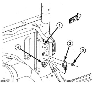
- Remove the trim from the inside of the lower right or left B-pillar (1). (Refer to 23 - Body/Interior/PANEL, B-Pillar Trim - Removal) .
- Remove the nut (3) that secures the side impact sensor (2) to the weld stud on the lower B-pillar.
- Remove the sensor from the weld stud on the inner B-pillar.
-
Disconnect the body
wire harness connector (4) from the sensor connector receptacle.
FRONT
To avoid serious or fatal injury
on vehicles equipped with airbags, disable the Supplemental Restraint
System (SRS) before attempting any steering wheel, steering column,
airbag, seat belt tensioner, impact sensor or instrument panel component
diagnosis or service. Disconnect and isolate the battery negative
(ground) cable, then wait two minutes for the system capacitor to
discharge before performing further diagnosis or service. This is
the only sure way to disable the SRS. Failure to take the proper precautions
could result in accidental airbag deployment.
WARNING:
To avoid serious or fatal injury,
never strike or drop the front impact sensor, as it can damage the
impact sensor or affect its calibration. The front impact sensor enables
the system to deploy the front Supplemental Restraint System (SRS)
components. If an impact sensor is accidentally dropped during service,
the sensor must be scrapped and replaced with a new unit. Failure
to observe this warning could result in accidental, incomplete, or
improper front SRS component deployment.
WARNING:
|
| NOTE: |
The front and side impact sensors are interchangeable. |
- Position the right or left front impact sensor (3) into the engine compartment.
- Reconnect the engine compartment wire harness connector (2) to the sensor connector receptacle.
- Carefully position the sensor onto the back (engine compartment side) of the front end module carrier (1) inboard of the right or left headlamp. Be certain that the anti-rotation pin on the back of the sensor is engaged in the clearance hole of the carrier.
- Install and tighten the screw (4) that secures the sensor to the back of the carrier. Tighten the screw to 8 N·m (70 in. lbs.).
-
Do not reconnect the
negative cable to the battery at this time. The Supplemental Restraint
System (SRS) Verification Test procedure should be performed following
service of any SRS component. (Refer to 10 - Restraints - Standard Procedure)
.
SIDE - FOUR-DOOR
To avoid serious or fatal injury
on vehicles equipped with airbags, disable the Supplemental Restraint
System (SRS) before attempting any steering wheel, steering column,
airbag, seat belt tensioner, impact sensor or instrument panel component
diagnosis or service. Disconnect and isolate the battery negative
(ground) cable, then wait two minutes for the system capacitor to
discharge before performing further diagnosis or service. This is
the only sure way to disable the SRS. Failure to take the proper precautions
could result in accidental airbag deployment.
WARNING:
To avoid serious or fatal injury,
never strike or drop the side impact sensor, as it can damage the
impact sensor or affect its calibration. The side impact sensor enables
the system to deploy the side Supplemental Restraint System (SRS)
components. If an impact sensor is accidentally dropped during service,
the sensor must be scrapped and replaced with a new unit. Failure
to observe this warning could result in accidental, incomplete, or
improper side SRS component deployment.
WARNING:
|
| NOTE: |
The front and side impact sensors are interchangeable. |
- Reconnect the body wire harness connector (4) to the side impact sensor (2) connector receptacle.
- Position the sensor onto the weld stud on the inner B-pillar (1). Be certain that the anti-rotation pin on the back of the sensor is engaged in the clearance hole of the B-pillar.
- Install and tighten the nut (3) that secures the sensor to the weld stud on the inner B-pillar. Tighten the nut to 8 N·m (70 in. lbs.).
- Reinstall the lower trim onto the inside of the B-pillar. (Refer to 23 - Body/Interior/PANEL, B-Pillar Trim - Installation) .
-
Do not reconnect the
negative cable to the battery at this time. The Supplemental Restraint
System (SRS) Verification Test procedure should be performed following
service of any SRS component. (Refer to 10 - Restraints - Standard Procedure)
.
SIDE - TWO-DOOR
To avoid serious or fatal injury
on vehicles equipped with airbags, disable the Supplemental Restraint
System (SRS) before attempting any steering wheel, steering column,
airbag, seat belt tensioner, impact sensor or instrument panel component
diagnosis or service. Disconnect and isolate the battery negative
(ground) cable, then wait two minutes for the system capacitor to
discharge before performing further diagnosis or service. This is
the only sure way to disable the SRS. Failure to take the proper precautions
could result in accidental airbag deployment.
WARNING:
To avoid serious or fatal injury,
never strike or drop the side impact sensor, as it can damage the
impact sensor or affect its calibration. The side impact sensor enables
the system to deploy the side Supplemental Restraint System (SRS)
components. If an impact sensor is accidentally dropped during service,
the sensor must be scrapped and replaced with a new unit. Failure
to observe this warning could result in accidental, incomplete, or
improper side SRS component deployment.
WARNING:
|
| NOTE: |
The front and side impact sensors are interchangeable. |
- Reconnect the body wire harness connector (4) to the side impact sensor (2) connector receptacle.
- Position the sensor onto the weld stud on the inner B-pillar (1). Be certain that the anti-rotation pin on the back of the sensor is engaged in the clearance hole of the B-pillar.
- Install and tighten the nut (3) that secures the sensor to the weld stud on the inner B-pillar. Tighten the nut to 8 N·m (70 in. lbs.).
- Reinstall the lower trim onto the inside of the B-pillar. (Refer to 23 - Body/Interior/PANEL, B-Pillar Trim - Installation) .
-
Do not reconnect the
negative cable to the battery at this time. The Supplemental Restraint
System (SRS) Verification Test procedure should be performed following
service of any SRS component. (Refer to 10 - Restraints - Standard Procedure)
.