SWITCH, Seat Belt
DESCRIPTION
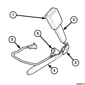 |
The driver side seat belt switch is a small, normally open, single pole, single throw, leaf contact momentary switch. The driver side switch is integral to the driver side front seat belt buckle (1). On domestic market vehicles, a second seat belt switch is integral to the passenger side front seat belt buckle. The passenger side seat belt switch consists of a fixed-position, Hall Effect Integrated Circuit (IC) chip and a small permanent magnet that are integral to the passenger side front seat belt buckle.
The front seat belt buckles are located on a molded plastic scabbard
(2) and secured along with the seat belt buckle or the buckle and
tensioner (4) mechanism by a screw near the back of the inboard front
seat cushion frame. The seat belt switches are connected to the vehicle
electrical system through a two-lead pigtail wire (5) and a two-way
(driver side) or four-way (passenger side) connector shared with the
buckle tensioner squib circuits on the front seat belt buckle-half,
which is connected to a connector and take out of the seat wire harness
routed beneath the front seat cushion. On the passenger side, a one
kilohm diagnostic resistor is connected in parallel with the Hall
Effect IC where the two pigtail wire leads connect to the IC pins.
The seat belt switches cannot be adjusted or repaired. If ineffective
or damaged, the entire front seat belt buckle-half or buckle and tensioner
unit must be replaced.
OPERATION
The driver side seat belt switch is designed to control a path to ground for the seat belt switch sense input of the Totally Integrated Power Module (TIPM). The passenger side seat belt switch is designed to control a sense input to the Occupant Restraint Controller (ORC). Both the mechanical driver side seat belt switch and the Hall Effect passenger side seat belt switch are actuated by the seat belt tip-half latch plate being engaged by the latch mechanism of the seat belt buckle-half.
The TIPM monitors the driver side seat belt switch status through the hard wired input, then controls the illumination of the seat belt indicator and the generation of audible electronic chime tones by sending electronic messages to the ElectroMechanical Instrument Cluster (EMIC) (also known as the Cab Compartment Node/CCN) over the Controller Area Network (CAN) data bus. The ORC monitors the passenger side seat belt switch and Occupant Detection Sensor (ODS) input status through hard wired inputs. If the ORC logic determines that the seat belt is not buckled while the seat is occupied, it sends an electronic message to the EMIC over the CAN data bus requesting seat belt indicator illumination.
The driver side seat belt switch receives ground through its connection to the body wire harness from another take out of the body wire harness. An eyelet terminal connector on that ground take out is secured under a ground screw. The driver side seat belt switch is connected in series between ground and the driver side seat belt switch sense input of the TIPM. The passenger side seat belt switch receives a clean ground from the ORC and is connected in series between the clean ground and the passenger side seat belt switch input of the ORC.
The hard wired circuits between the seat belt switches and the TIPM (driver side) or ORC (passenger side) may be diagnosed using conventional diagnostic tools and procedures. Refer to the appropriate wiring information. However, conventional diagnostic methods will not prove conclusive in the diagnosis of the switches or the electronic controls and communication between other modules and devices that provide features of the Supplemental Restraint System (SRS). The most reliable, efficient and accurate means to diagnose the seat belt switches or the electronic controls and communication related to seat belt switch operation requires the use of a diagnostic scan tool. Refer to the appropriate diagnostic information.