11 - Exhaust System
GAS ENGINES
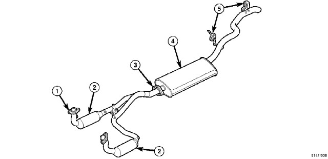 EXHAUST SYSTEM - TYPICAL - GAS ENGINES |
|
1 - EXHAUST FLANGE 2 - CATALYTIC CONVERTER 3 - FRONT EXHAUST PIPE ASSY-TO-MUFFLER FLANGE 4 - MUFFLER 5 - INSULATOR |
The basic exhaust system consists of a exhaust pipe assembly with catalytic converters (2), muffler (4) and tailpipe assembly and heat shields.
The exhaust system must be properly aligned to prevent stress, leakage and body contact. Minimum clearance between any exhaust component and the body or frame is 25 mm (1.0 in.). If the system contacts any body panel, it may amplify objectionable noises from the engine or body.
When inspecting an exhaust system, critically inspect for cracked or loose joints, stripped screw or bolt threads, corrosion damage and worn, cracked or broken hangers. Replace all components that are badly corroded or damaged. DO NOT attempt to repair.
When replacement is required, use original equipment parts (or equivalent). This will assure proper engine function and system alignment.
Avoid application of rust prevention
compounds or undercoating materials to exhaust system floor pan exhaust
heat shields. Light overspray near the edges is permitted. Application
of coating will result in excessive floor pan temperatures and objectionable
fumes.
CAUTION:
2.8L DIESEL
Avoid application of rust prevention
compounds or undercoating materials to exhaust system floor pan exhaust
heat shields. Light overspray near the edges is permitted. Application
of coating will result in excessive floor pan temperatures and objectionable
fumes.
CAUTION:
The diesel engine exhaust system consists of an engine exhaust manifold, turbocharger, EGR valve with intercooler, front exhaust pipe with catalytic converter, muffler and tailpipe assembly.
The exhaust system must be properly aligned to prevent stress, leakage and body contact. The exhaust components should be kept a minimum of 25.4 mm (1.0 in.) away from the body and frame. If the system contacts any body panel, it may amplify objectionable noises from the engine or body.
DIAGNOSIS AND TESTING - GAS ENGINE
 |
EXHAUST SYSTEM DIAGNOSIS CHART
|
CONDITION |
POSSIBLE CAUSE |
CORRECTION |
||
|---|---|---|---|---|
|
Excessive Exhaust Noise or Leaking Exhaust Gases |
1. Leaks at pipe joints. |
1. Tighten clamps/bolts to specified torque at leaking joints. |
||
|
2. Rusted or blown out muffler. |
2. Replace muffler. Inspect exhaust system. |
|||
|
3. Broken or rusted out exhaust pipe. |
3. Replace exhaust pipe. |
|||
|
4. Exhaust pipe leaking at manifold flange. |
4. Tighten/replace flange attaching nuts/bolts. |
|||
|
5. Exhaust manifold cracked or broken. |
5. Replace exhaust manifold. |
|||
|
6. Leak between exhaust manifold and cylinder head. |
6. Tighten exhaust manifold to cylinder head bolts. |
|||
|
7. Catalytic converter rusted or blown out. |
7. Replace catalytic converter assembly. |
|||
|
8. Restriction in exhaust system. |
8. Remove restriction, if possible. Replace restricted part if necessary. |
|||
|
When servicing and/or replacing
exhaust system components, disconnect the oxygen sensor connector(s).
Allowing the exhaust to hang by the oxygen sensor wires will damage
the harness and/or oxygen sensor. |
||||
DIESEL ENGINE
On high mileage vehicles it is
normal to see some exhaust staining around the turbocharger control
rod area. This is not a sign of turbocharger failure.
CAUTION:
EXHAUST SYSTEM DIAGNOSIS CHART
|
CONDITION |
POSSIBLE CAUSE |
CORRECTION |
|---|---|---|
|
EXCESSIVE EXHAUST NOISE OR LEAKING EXHAUST GASES |
1. Leaks at pipe joints. |
1. Tighten clamps/bolts at leaking joints. |
|
2. Rusted or blown out muffler. |
2. Replace muffler. Inspect exhaust system. |
|
|
3. Broken or rusted out exhaust pipe. |
3. Replace exhaust pipe. |
|
|
4. Exhaust pipe leaking at manifold flange. |
4. Tighten/replace flange attaching nuts/bolts. |
|
|
5. Exhaust manifold cracked or broken. |
5. Replace exhaust manifold. |
|
|
6. Leak between exhaust manifold and cylinder head. |
6. Tighten exhaust manifold to cylinder head bolts. Replace gasket if necessary. |
|
|
7. Turbocharger mounting flange cracked. |
7. Remove turbocharger and inspect. (Refer to 9 - ENGINE/MANIFOLDS/EXHAUST MANIFOLD - REMOVAL). |
|
|
8. Restriction in exhaust system. |
8. Remove restriction, if possible. Replace restricted part if necessary. |
|
|
9. EGR pipe(s) leak. |
9. Tighten bolts. Replace gasket. |
|
|
10. EGR assembly leak. |
10. Tighten bolts. Replace gaskets. |
|
|
Drivability Concern - Turbo |
1. Vacuum hose disconnected. |
1. Check connections, replace as necessary. |
|
2. Vacuum system leaks. |
2. Inspect for damage. Check for leaks, replace as necessary. |
|
|
3. Boost pressure solenoid filter clogged. |
3. Replace the filter. |
SPECIFICATIONS
|
DESCRIPTION |
N·m |
Ft. Lbs. |
|---|---|---|
|
Bolts, Crossmember to Sill |
42 |
31 |
|
Nuts, Crossmember to Transmission Mount |
22 |
16 |
|
Nuts/Bolt, Exhaust Manifold to Engine |
36 |
27 |
|
Nuts, Exhaust Pipe to Catalytic Converter Flange |
27 |
19 |
|
Nuts, Catalytic Converter to Turbocharger |
27 |
19 |
|
Bolt, DPF to Catalytic Converter |
32 |
24 |
|
Bolts, DPF to Muffler |
32 |
24 |
|
Clamp, Tailpipe to Rear Tailpipe Hanger |
27 |
20 |
|
Oxygen Sensors |
50 |
37 |
|
Heat Shields |
45 |
33 |