22 - Tires and Wheels
- DIAGNOSIS AND TESTING - TIRE AND WHEEL VIBRATION
- MATCH MOUNTING
- TIRE AND WHEEL BALANCE
- ROTATION
- SPECIAL TOOLS
DIAGNOSIS AND TESTING - TIRE AND WHEEL VIBRATION
Tire and wheel imbalance, runout and tire road force variation can cause vehicles to exhibit steering wheel vibration and/or seat vibration.
VISUAL INSPECTION
Visual inspection of the vehicle is recommended prior to road testing or performing any other procedure. Raise and support the vehicle (Refer to 04 - Vehicle Quick Reference/Hoisting - Standard Procedure) .
Inspect for the following:
- Verify correct (OEM) wheel and tire, as well as presence of wheel weights.
- Inspect tires and wheels for damage, mud packing and unusual wear; correct as necessary.
- Check and adjust tire air pressure to the pressure listed on the label attached to the driver's door opening.
ROAD TEST
| NOTE: |
If a Noise & Vibration Analyzer is available, use it to diagnosis the issue during the road test. |
| NOTE: |
If the vehicle has been sitting for an extended period of time it is recommended to drive to warm the tires. This process could eliminate flat spots that can cause vibration. |
Road test vehicle on a smooth road at and near the designated speed where legal speed limits allow. Lightly place hands on steering wheel at the 10:00 and 2:00 positions and observe for:
- Steering wheel oscillation: clockwise/counterclockwise
- Steering wheel high frequency movement: rapid vibration up and down
- Seat high frequency movement: rapid vibration up and down
To rule out vibrations due to brakes or powertrain:
- Lightly apply brakes at the designated speed; if vibration occurs or is enhanced, vibration is likely due to a brake concern.
- Shift transmission into neutral while vibration is occurring; if vibration is eliminated, vibration is likely due to a powertrain concern (Refer to 03 - DIFFERENTIAL AND DRIVELINE).
TIRE/WHEEL BALANCE AND ROAD FORCE VARIATION
| NOTE: |
If wheel balance equipment is capable of testing tire road force variation and the tire/wheel assemblies are within specification, place the tires with the greater road force variation on the rear of the vehicle. |
Balance the tire and wheel assemblies as necessary, and if wheel balance equipment is capable, also test for tire and wheel runout and road force variation following the wheel balancer manufacturer's instructions and using the information listed in Tire And Wheel Balance (Refer to 22 - Tires and Wheels - Standard Procedure) . Repeat the road test above to verify the vibration is repaired.
MATCH MOUNTING
Wheels and tires that are mounted means that the high spot of the tire is matched to the low spot on the wheel rim. Each are marked with a bright colored temporary label on the outboard surface for alignment. The wheel is also marked permanently on the inside of the rim in the tire well. This permanent mark may be a paint dot or line, a permanent label or a stamped impression such as an X. An optional location mark is a small spherical indentation on the vertical face of the outboard flange on some non styled base steel wheels. The tire must be removed to locate the permanent mark on the inside of the wheel.
Before dismounting a tire from its wheel, a reference mark should be placed on the tire at the valve stem location. This reference will ensure that it is remounted in the original position on the wheel.
 |
- Remove the tire and wheel assembly from the vehicle and mount on a service dynamic balance machine.
-
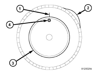
Measure the total runout on the center of the tire tread rib (3) with a dial indicator. Record the indicator reading. Mark the tire to indicate the high spot (2). Place a mark on the tire at the valve stem (4) location (1).
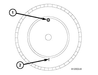
- Break down the tire and remount it 180 degrees on the rim (1)(2).
-
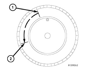
Measure the total indicator runout again. Mark the tire to indicate the high spot.
- If runout is still excessive, the following procedures must be done.
- If the high spot is within 101.6 mm (4.0 in.) of the first spot and is still excessive, replace the tire.
- If the high spot is within 101.6 mm (4.0 in.) of the first spot on the wheel, the wheel may be out of specifications. Refer to Wheel and Tire Runout.
-
If the high spot is NOT within 101.6 mm (4.0 in.) of either high spot, draw an arrow on the tread from second high spot (1) to first (2). Break down the tire and remount it 90 degrees on rim in that direction. This procedure will normally reduce the runout to an acceptable amount, if not replace the rim.
TIRE AND WHEEL BALANCE
| NOTE: |
Always verify the wheel and tire balance before removing any wheel weights. If assembly is within specification and weights are not corroded or loose, do not remove weights. The process of removing and adding weight could damage wheel protective coating. |
| NOTE: |
Balance and road force variation equipment must be calibrated and maintained per equipment manufacturer's specifications. |
| NOTE: |
If a tire sealant & inflator kit was used to temporarily repair small punctures then the tire must be removed from wheel and all the sealant must be removed with a water damped cloth before repairing & balancing the assembly. |
| NOTE: |
Some wheels may not have an outer flange. Apply adhesive weights on midplane surface to balance. |
 |
| NOTE: | Use of the proper collet will prevent potential damage to the Chrome Clad wheels. |
| NOTE: |
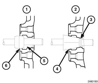
Balance equipment could read an incorrect balance result when measuring Chrome Clad wheels. This is caused by the equipments mounting cone/collet contacting the cladding or the cone/collet is not balanced. A dual-taper collet (1) type wheel centering tool is recommended as opposed to a high-taper cone (2) type wheel centering tool. Always use the manufacturer’s recommended balance equipment. |
| NOTE: |
If wheel balance equipment is capable of testing tire road force variation and the tire/wheel assemblies are within specification, place the tires with the greater road force variation on the rear of the vehicle. |
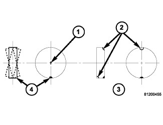 |
For dynamic balancing (recommended), the
balance equipment is designed to indicate the location and amount
of weight to be applied to both the inner and outer rim flanges (2).
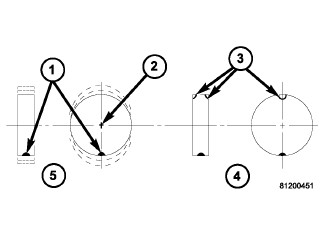 |
For static balancing (not recommended), find the location of the heavy spot causing the imbalance (1).
Counter balance the wheel directly opposite the heavy spot. Determine
weight required to counterbalance the area of imbalance. Place half
of this weight on the inner rim flange and the other half on the outer rim flange
(3) at the predetermined spots.
Aluminum wheels use a different type wheel weight than steel wheels. Be sure to use the correct wheel weight for the wheel type.
Always verify the balance. When using off-vehicle equipment, remount the tire and wheel assembly 180 degrees on the balancer spindle and recheck balance. Balance variation from one spot to the other should not be more than 0.125 (⅛) ounce. If variation is more than 0.125 ounce, balancing equipment could be malfunctioning, or the wrong collet/cone may have been used.
If difficult to balance, break down the tire and wheel assembly and check for loose debris inside the tire. Prior to disassembly, mark (index) the tire at the valve stem. Use this mark in order to remount the tire in its original orientation with respect to the wheel.
ROTATION
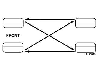 |
Tires on the front and rear operate at different loads and perform different steering, driving, and braking functions. For these reasons they wear at unequal rates and tend to develop irregular wear patterns. These effects can be reduced by rotating the tires at regular intervals. The benefits of tire rotation are:
The suggested method of tire rotation is shown in graphic. Other rotation methods can be used, but they will not provide all the tire longevity benefits.
SPECIAL TOOLS
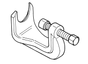 |
8677 - Remover, Ball Joint Originally Shipped In Kit Number(s) 8685, 8685CC, 8712, 9973, 9974, 9975. |
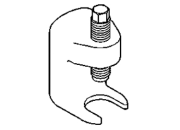 |
C-4150A - Press, Ball Joint Originally Shipped In Kit Number(s) 6672, 6745. |