Tire Pressure Monitoring
DESCRIPTION
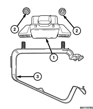 |
The Tire Pressure Monitoring (TPM) system monitors air pressure in the four road tires (excludes spare). Pressure in the spare tire is not monitored.
There are two tire pressure monitoring systems available, a base system and a premium system. The base system does not specify how many tires are low or where they are located. The premium system does so.
Both TPM systems consist of tire pressure monitoring sensors attached to each road wheel through the valve stem mounting hole and a TPM module. The TPM module (1) is fixed to a metal bracket (3) mounted onto the rear crossmember frame. The TPM module decodes the RF signals transmitted by each of the vehicle’s tire pressure sensors. The decoded information is used to determine if "warning" or "fault" conditions exist within the TPM system.
Upon detection of a warning or fault condition, the TPM module will send a request to the module that controls the indicator lamp and the text display via the vehicle bus system to illuminate or flash the indicator lamp. Also, upon detection of a warning or fault condition, the electronic display will send a request to sound the "chime".
The TPM module will store all warning and fault conditions, placard pressure values and low pressure threshold values (lamp ON and OFF) in memory that can be accessed through diagnostic communication. If new sensors are introduced to the vehicle, the data stored for the sensor being replaced will be deleted once the new sensor id has been learned.
The TPM module will store all wheel sensor ID’s and locations and faults in memory that can be accessed through diagnostic communication.
The TPM module automatically learns and stores the sensor IDs while driving “within 20 minutes continuously above 20 mph (32 km/h)” after a sensor has been replaced. The learning sequence will initiate when the vehicle has been stopped for more than 20 minutes.
| NOTE: |
A new sensor ID can also be programmed directly into the TPM module by using a RKE-TPM Analyzer in conjunction with a Scan Tool. Once the new sensor ID has been programmed, the vehicle will need to be driven above 20 mph until the fault is no longer active (lamp extinguishes) and display is updated (for up to 20 minutes). |
| NOTE: |
Using a TPM-RKE Analyzer can take up to a minute to force a transmission from a sensor. |
OPERATION
The Tire Pressure Monitoring (TPM) system monitors air pressure in the four road tires, or if the vehicle original equipment includes a full size matching spare, then all five tires. Pressure in the spare tire is not monitored with a compact spare or a "non-matching spare.
There are two tire pressure monitoring systems available, a base system and a premium system. The base system does not specify how many tires are low or where they are located. The premium system does indicate which tire is low.
The recommended "Placard Pressure", "Low-pressure Threshold" (Low Pressure ON) and “Hysteresis Pressure” values for the tires installed on the vehicle, are learned by the TPM module configuration during the initial Manufacturing Plant Process, or during a service procedure, as required.
To determine the pressure thresholds for a vehicle, refer to the Tire Inflation Pressure (Placard) Label, and then apply the placard pressure to the following table. The Low Pressure OFF Threshold is defined as the Low Pressure ON Threshold plus the Hysteresis Pressure value.
For further information, refer to the Owners Manual or the Appropriate Diagnostic Information.
TPM THRESHOLD PRESSURES
| NOTE: |
To determine the pressure thresholds for a vehicle, refer to the Tire Inflation Pressure (Placard) Label found on the Driver's B-Pillar, then apply the placard pressure to the following table. |
|
Placard Pressure (Cold) (PSI) |
Low Pressure ON Threshold (PSI) |
Low Pressure OFF Threshold (PSI) |
|---|---|---|
|
28 |
22 |
26 |
|
29 |
23 |
27 |
|
30 |
24 |
28 |
|
31 |
25 |
29 |
|
32 |
25 |
29 |
|
33 |
26 |
30 |
|
34 |
27 |
31 |
|
35 |
28 |
32 |
|
36 |
29 |
33 |
|
37 |
29 |
34 |
|
38 |
30 |
35 |
|
39 |
31 |
36 |
|
40 |
32 |
37 |
|
41 |
33 |
38 |
|
42 |
34 |
39 |
|
43 |
35 |
40 |
|
44 |
36 |
41 |
|
45 |
36 |
41 |
|
46 |
37 |
43 |
|
47 |
38 |
44 |
|
48 |
38 |
45 |
|
49 |
39 |
45 |
|
50 |
40 |
47 |
|
51 |
41 |
48 |
|
55 |
44 |
52 |
|
60 |
48 |
57 |
|
65 |
52 |
62 |
|
70 |
56 |
67 |
|
75 |
60 |
72 |
|
80 |
64 |
77 |
TIRE PRESSURE MONITORING SYSTEM
All Tire Pressure Monitoring System Faults are specific to one location. If a "BATTERY LOW" fault is detected it will cause a loss of signal fault. If a "SENSOR FAILURE" fault is detected, the location will be displayed (Premium Systems). The appropriate sensor/transmitter can then be replaced. If a single sensor/transmitter cannot be detected by the WCM, replace that sensor transmitter. If none of the sensors/transmitters can be detected, refer to symptoms in the WCM section. For additional system description and diagnosis, refer to Tire Pressure Monitoring in the Body Diagnostic manual .
TIRE PRESSURE
Check the tire pressure yellow telltale in the instrument cluster. If the yellow telltale is illuminating continuously, adjust the air pressure as necessary to that listed on the Tire Inflation Pressure Label (Placard) provided with the vehicle. After adjusting air pressure in a tire, allow approximately two minutes for the message or yellow telltale to go out. Inspect all the tires for leaks. A water "dunk tank" or other water test may be used as long as any water at the valve core is removed once the procedure is complete. The water can be easily expelled from the core area by pushing in on the core for several seconds, allowing escaping air to drive out any moisture. Reinflate the tire as necessary. Always make sure the original valve stem cap is securely installed to keep moisture out of the sensor. If the yellow telltale is still illuminating continuously or if the yellow telltale is flashing on/off for 60 seconds, once every ten minutes while drive, there is a system fault detected (Refer to 22 - Tires and Wheels/Tire Pressure Monitoring - Diagnosis and Testing) .
SPECIFICATIONS
| DESCRIPTION | N·m |
Ft. Lbs. |
In. Lbs. |
|---|---|---|---|
|
Tire Pressure Module Bracket Mounting Bolt |
9 |
— |
80 |