For a complete wiring diagram, refer to the Wiring Information.
Possible Causes
When Monitored:
With the
ignition on.
Set Condition:
The Occupant
Restraint Controller (ORC) monitors the resistance of the Left Seat
Squib circuits. The ORC will set this DTC if it detects low resistance
of the Left Seat Squib circuits.
Possible Causes
(R31) LEFT SEAT SQUIB
LINE 1 CIRCUIT SHORTED TO GROUND
(R33) LEFT
SEAT SQUIB LINE 2 CIRCUIT SHORTED TO GROUND
LEFT SEAT SQUIB AIRBAG
OCCUPANT RESTRAINT
CONTROLLER (ORC)
1.
DETERMINE ACTIVE OR STORED DTC
NOTE:
Make sure that the battery is fully charged.
NOTE:
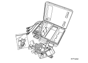
The scan tool, SRS Load Tool Kit 8443A, and DVOM are required to perform the following test.
2.
CHECK FOR SHORTED SQUIB CIRCUITS AT THE LEFT SEAT SQUIB AIRBAG
WARNING:
Turn the ignition off disconnect
the 12-volt battery and wait two minutes before proceeding. Failure
to follow these instructions may result in possible serious or fatal
injury.
1.
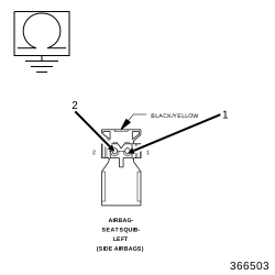
Disconnect the Left Seat Squib Airbag connector.
WARNING:
To avoid serious or fatal injury,
do not place an intact non-deployed Left Seat Squib Airbag face down
on a hard surface, the airbag will propel into the air if accidentally
deployed.
NOTE:
Check connectors - Clean and repair as necessary.
2.
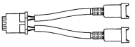
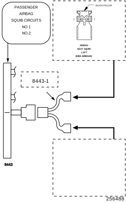
Connect the SRS Load Tool Kit
8443A
and SRS Load Tool Jumper
8443-1
to the Left Seat Squib Airbag connector.
WARNING:
Turn the ignition on, then reconnect
the 12-volt battery and wait two minutes before proceeding. Failure
to follow these instructions may result in possible serious or fatal
injury.
3.
With the scan tool, read the active ORC DTC.
Does the scan tool display: B1C27-LEFT SIDE SEAT THORAX SQUIB 1 LOW?
Turn the ignition off disconnect
the 12-volt battery and wait two minutes before proceeding. Failure
to follow these instructions may result in possible serious or fatal
injury.
Replace the Left Seat Squib Airbag in accordance with the Service Information.
3.
CHECK (R31) LEFT SEAT SQUIB LINE 1 CIRCUIT OR (R33) LEFT SEAT SQUIB LINE 2 CIRCUIT FOR A SHORT TO GROUND
WARNING:
Turn the ignition off disconnect
the 12-volt battery and wait two minutes before proceeding. Failure
to follow these instructions may result in possible serious or fatal
injury.
1.
Disconnect the SRS Load Tool Kit
8443A
and SRS Load Tool Jumper
8443-1
from the Left Seat Squib Airbag connector.
2.
Disconnect the ORC connectors.
NOTE:
Check connectors - Clean and repair as necessary.
3.
Connect the SRS Load Tool Adaptor
8443-32-L
to the ORC connectors.
4.
Measure the resistance of the (R31) Left Seat Squib Line 1 circuit between ground and the SRS Load Tool Adaptor
8443-32-L
cavity C2-6.
5.
Measure the resistance of the (R33) Left Seat Squib Line 2 circuit between ground and the SRS Load Tool Adaptor
8443-32-L
cavity C2-5.
Is the resistance below 10K Ohms on either circuit?
Yes
Repair the Left Seat Squib circuits with resistance below 10K Ohms for a short to ground.
If the Occupant Restraint Controller
(ORC) is dropped at any time, it must be replaced. Failure to take
the proper precautions can result in accidental airbag deployment.
Failure to follow these instructions may result in possible serious
or fatal injury.
Replace the ORC in accordance with the Service Information.
Diagnose and repair all active codes before diagnosing stored codes. Refer to the Table of Contents in this Section for a complete list of airbag system diagnostic procedures.
1.
With the scan tool, record and erase all Airbag System Module DTC.
WARNING:
Turn the ignition off disconnect
the 12-volt battery and wait two minutes before proceeding. Failure
to follow these instructions may result in possible serious or fatal
injury.
2.
Using the wiring diagram/schematic as a guide, inspect the related wiring and connectors for chafed, pierced, pinched, and partially broken wires, and for broken, bent, pushed out, corroded, and contaminated terminals. Repair as necessary.
3.
Reconnect all disconnected components and harness connectors.
WARNING:
Turn the ignition on, then reconnect
the 12-volt battery and wait two minutes before proceeding. Failure
to follow these instructions may result in possible serious or fatal
injury.
4.
With the scan tool, monitor for active codes while performing the following:
Wiggle the wiring harness and connectors of the related airbag circuit.
Continue the test until either a code becomes active or the problem area is isolated.
5.
In the previous steps you have attempted to recreate the conditions responsible for setting the DTC in question/causing the intermittent condition.