U0175-LOST COMMUNICATION W/RIGHT SIDE SATELLITE ACCELERATION SENSOR 1
 |
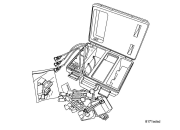
For a complete wiring diagram, refer to the Wiring Information.
Theory of Operation
The location of this right side impact sensor 1 is in the B-pillar just past the first row seating. (Refer to 10 - Restraints - Description) . The impact sensors perform their own self test using power supplied by the Occupant Restraint Controller (ORC) then communicate this status back to the ORC with periodic updates. The repair of this fault condition involves verifying the integrity of the wiring between the ORC and the sensor. If the scan tool shows this DTC has a Stored history of setting then the right side impact sensor is to be replaced. A short to voltage fault on the right side impact sensor 1 sensor wiring can cause a loss of comm impact sensor 2 code to set and the possible replacement of a good right side impact sensor 2. The right side impact 1, and 2 sensors are wired in a daisy chain pattern. The short to battery fault in a loss of comm or internal circuit failure of the side impact sensor 1 can cause the impact sensor 2 on the same side to set a loss of comm code.
-
When Monitored:
The Occupant Restraint Controller (ORC) continuously communicates with the Right Side Impact Sensor 1 over the sensor signal circuit. The sensor communication and on board diagnostics are powered by the ORC signal.
-
Set Condition:
This code will set, if the ORC and the Right Side Impact Sensor 1 do not establish and maintain valid data communications.
Possible Causes |
|---|
| (R14) SIGNAL CIRCUIT SHORTED TO VOLTAGE |
| (R14) SIGNAL CIRCUIT SHORTED TO GROUND |
| (R14, R16) RIGHT SIDE IMPACT SENSOR 1 CIRCUITS SHORTED TOGETHER |
| (R16) RIGHT SIDE IMPACT SENSOR 1 GROUND CIRCUIT OPEN |
| (R14) RIGHT SIDE IMPACT SENSOR 1 SIGNAL CIRCUIT OPEN |
| OCCUPANT RESTRAINT CONTROLLER (ORC) |
1. VERIFY THAT DTC U0175-LOST COMMUNICATION W/RIGHT SIDE SATELLITE ACCELERATION SENSOR 1
Turn the ignition off disconnect
the 12-volt battery and wait two minutes before proceeding. Failure
to follow these instructions may result in possible serious or fatal
injury.
WARNING:
| NOTE: | Using the wiring diagram/schematic as a guide check all related splices and connectors for signs of water intrusion, corrosion, pushed out or bent terminals, and correct pin tension. |
| NOTE: | If after the harness inspection it appears the impact sensor connector is only seated halfway. Reseat the harness connector into the impact sensor and lock the tab. |
Turn the ignition on, then reconnect
the 12-volt battery and wait two minutes before proceeding. Failure
to follow these instructions may result in possible serious or fatal
injury.
WARNING:
| NOTE: | Make sure the battery is fully charged. |
| 1. | Turn the ignition on. |
| 2. | With the scan tool, read ORC DTC. |
Does the scan tool display active B1B75-RIGHT SIDE SATELLITE ACCELERATION SENSOR 1 INTERNAL, U0175-LOST COMMUNICATION W/RIGHT SIDE SATELLITE ACCELERATION SENSOR 1, U0176-LOST COMMUNICATION W/RIGHT SIDE SATELLITE ACCELERATION SENSOR 2 DTC?
Yes
- Check for all other internal and lost communication codes indicated in the right side impact sensor daisy chain wiring, starting with B1B75-RIGHT SIDE SATELLITE ACCELERATION SENSOR 1 INTERNAL, then DTC U0175-LOST COMMUNICATION W/RIGHT SIDE SATELLITE ACCELERATION SENSOR 1. (Refer to 28 - DTC-Based Diagnostics/CONTROLLER, Occupant Restraint (ORC) - Diagnosis and Testing). Then Go To 2
No
- Go To 9
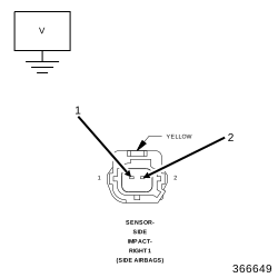
2. CHECK THE (R14) AND (R16) RIGHT SIDE IMPACT SENSOR 1 CIRCUITS FOR A SHORT TO VOLTAGE
 |
Turn the ignition off, disconnect
the 12-volt battery and wait two minutes before proceeding. Failure
to follow these instructions may result in possible serious or fatal
injury.
WARNING:
| 1. | Disconnect the Right Side Impact Sensor 1 harness connector. |
| 2. | Disconnect the ORC harness connectors. |
| 3. | Connect the SRS Load Tool Adaptor 8443-32-L to the ORC harness connector. |
Turn the ignition on, then reconnect
the 12-volt battery and wait two minutes before proceeding. Failure
to follow these instructions may result in possible serious or fatal
injury.
WARNING:
| 4. | Measure the voltage of the (R14) Right Side Impact Sensor 1 Signal circuit and the (R16) Sensor Ground circuit at the Right Side Impact Sensor 1 harness connector. |
Is there any voltage present?
Yes
-
WARNING: Turn the ignition off, disconnect the 12-volt battery and wait two minutes before proceeding. Failure to follow these instructions may result in possible serious or fatal injury.
- Repair the (R14) and (R16) Right Side Impact Sensor 1 circuits for a short to voltage.
- Perform the AIRBAG SYSTEM VERIFICATION TEST. (Refer to 28 - DTC-Based Diagnostics/CONTROLLER, Occupant Restraint (ORC) - Standard Procedure).
No
-
Go To 3
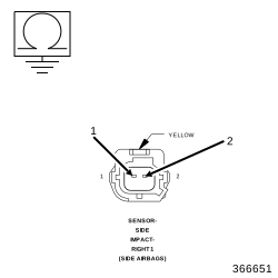
3. CHECK THE (R14) AND (R16) RIGHT SIDE IMPACT SENSOR 1 CIRCUITS FOR A SHORT TO GROUND
 |
Turn the ignition off, disconnect
the 12-volt battery and wait two minutes before proceeding. Failure
to follow these instructions may result in possible serious or fatal
injury.
WARNING:
| 1. | Measure the resistance between ground and the (R14) Right Side Impact Sensor 1 Signal circuit at the Right Side Impact Sensor 1 harness connector. |
| 2. | Measure the resistance between ground and the (R16) Right Side Impact Sensor Ground circuit at the Right Side Impact Sensor 1 harness connector. |
Is the resistance below 100K Ohms on either circuit?
Yes
- Repair the (R14) Right Side Impact Sensor 1 Signal or (R16) Right Side Impact Sensor 1 Ground circuit for a short to ground.
- Perform the AIRBAG SYSTEM VERIFICATION TEST. (Refer to 28 - DTC-Based Diagnostics/CONTROLLER, Occupant Restraint (ORC) - Standard Procedure).
No
-
Go To 4
4. CHECK THE (R14) AND (R16) RIGHT SIDE IMPACT SENSOR CIRCUITS FOR A SHORT TOGETHER
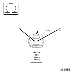 |
| 1. | Measure the resistance between the (R14) Right Side Impact Sensor 1 Signal circuit and the (R16) Sensor Ground circuit at the Right Side Impact Sensor 1 harness connector. |
Is the resistance below 100K Ohms?
Yes
- Repair the (R14) and (R16) Right Side Impact Sensor 1 circuits shorted together.
- Perform the AIRBAG SYSTEM VERIFICATION TEST. (Refer to 28 - DTC-Based Diagnostics/CONTROLLER, Occupant Restraint (ORC) - Standard Procedure).
No
-
Go To 5
5. CHECK THE (R16) RIGHT SIDE IMPACT SENSOR 1 GROUND CIRCUIT FOR AN OPEN OR HIGH RESISTANCE
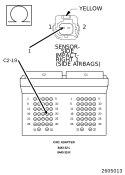 |
| 1. | Measure the resistance of the (R16) Right Side Impact Sensor 1 Ground circuit between the Right Side Impact Sensor 1 harness connector and the SRS Load Tool Adaptor 8443-32-L . |
Is the resistance below 1 Ohm?
Yes
- Go To 6
No
- Repair the (R16) Right Side Impact Sensor 1 Ground circuit for an open or high resistance.
-
Perform the AIRBAG SYSTEM VERIFICATION TEST. (Refer to 28 - DTC-Based Diagnostics/CONTROLLER, Occupant Restraint (ORC)
- Standard Procedure).
6. CHECK THE (R14) RIGHT SIDE IMPACT SENSOR 1 CIRCUIT FOR AN OPEN OR HIGH RESISTANCE
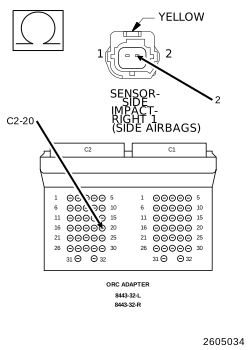 |
| 1. | Measure the resistance of the (R14) Right Side Impact Sensor 1 Signal circuit between the Right Side Impact Sensor 1 harness connector and the SRS Load Tool Adaptor 8443-32-L . |
Is the resistance below 1 Ohm?
Yes
- Go To 7
No
- Repair the (R14) Right Side Impact Sensor 1 Signal circuit for an open or high resistance.
-
Perform the AIRBAG SYSTEM VERIFICATION TEST. (Refer to 28 - DTC-Based Diagnostics/CONTROLLER, Occupant Restraint (ORC)
- Standard Procedure).
7. CHECK OPERATION OF THE RIGHT SIDE IMPACT SENSOR 1
| 1. | Replace the Right Side Impact Sensor 1. |
| 2. | Reconnect the vehicle body harness to the impact sensor. |
| 3. | Remove any special tools or jumper wires and reconnect all previously disconnected components - except the Battery. |
Turn the ignition on, then reconnect
the 12-volt battery and wait two minutes before proceeding. Failure
to follow these instructions may result in possible serious or fatal
injury.
WARNING:
| 4. | Connect the scan tool to the Data Link Connector - use the most current software available. |
| 5. | Use the scan tool and erase the stored codes in all airbag system modules. |
| 6. | Turn the Ignition Off, and wait 15 seconds before turning the Ignition On. |
| 7. | Wait one minute, and read active codes and if there are none present read the stored codes. |
Did the active Right Side Impact Sensor 1 DTC return?
Yes
- Go To 8
No
- Repair is complete.
- Perform the AIRBAG SYSTEM VERIFICATION TEST. (Refer to 28 - DTC-Based Diagnostics/CONTROLLER, Occupant Restraint (ORC) - Standard Procedure).
8. REPLACE THE OCCUPANT RESTRAINT CONTROLLER
Turn the ignition off, disconnect
the 12-volt battery and wait two minutes before proceeding. Failure
to follow these instructions may result in possible serious or fatal
injury.
WARNING:
If there are no possible causes remaining, view repair.
Repair
-
WARNING: If the Occupant Restraint Controller (ORC) is dropped at any time, it must be replaced. Failure to follow these instructions may result in possible serious or fatal injury.
- Replace the Occupant Restraint Controller in accordance with Service Instructions.
- Perform the AIRBAG SYSTEM VERIFICATION TEST. (Refer to 28 - DTC-Based Diagnostics/CONTROLLER, Occupant Restraint (ORC) - Standard Procedure).
9. TEST FOR AN INTERMITTENT CONDITION
| 1. | With the scan tool, record and erase all DTC from all Airbag modules. |
| 2. | If any ACTIVE codes are present they must be resolved before diagnosing any stored codes. |
Turn the ignition off, disconnect
the 12-volt battery and wait two minutes before proceeding. Failure
to follow these instructions may result in possible serious or fatal
injury.
WARNING:
| 3. | Using the wiring diagram/schematic as a guide, inspect the wiring and harness connectors. |
| 4. | Look for chafed, pierced, pinched, or partially broken wires and broken, bent, pushed out, spread, corroded, or contaminated terminals. |
| 5. | The following additional checks may assist you in identifying a possible intermittent problem. |
| 6. | Reconnect any disconnected components and harness connector. |
Turn the ignition on, then reconnect
the 12-volt battery and wait two minutes before proceeding. Failure
to follow these instructions may result in possible serious or fatal
injury.
WARNING:
| 7. | With the scan tool monitor active codes as you work through the following steps. |
Maintain a safe distance from all
airbags while performing the following steps. Failure to follow these
instructions may result in possible serious or fatal injury.
WARNING:
| 8. | Wiggle the wiring harness and harness connectors of the related airbag circuit or component. |
| 9. | If codes are related to the Driver Airbag circuits, rotate the steering wheel from stop to stop. |
| 10. | If only stored codes return continue the test until the problem area has been isolated. |
| 11. | In the previous steps you have attempted to recreate the conditions responsible for setting active DTC in question. |
Are any ACTIVE DTC present?
Yes
- (Refer to 28 - DTC-Based Diagnostics/CONTROLLER, Occupant Restraint (ORC) - Diagnosis and Testing) and perform the appropriate diagnostic procedure.
No