C1073-ABS PUMP MOTOR CONTROL CIRCUIT
 |
For a complete wiring diagram, refer to the Wiring Information.
| NOTE: |
The Electronic Stability Control (ESC) may also be referred to as Electronic Stability Program (ESP) depending on the vehicle model year and configuration. Certain components may also reference ESP, ESC, or use the traction control symbol. |
-
When Monitored:
When the ABS Pump Motor is activated.
-
Set Condition:
The ABS Module detects low pump motor feedback voltage with actuation of the pump motor relay.
Possible Causes |
|---|
| BLOWN PUMP FUSE |
| WIRING HARNESS, TERMINAL, CONNECTOR DAMAGE |
| HIGH RESISTANCE IN B+ CIRCUITS |
| HIGH RESISTANCE IN GROUND CIRCUITS |
| INTEGRATED CONTROL UNIT |
1. CHECK FOR A DTC C1073-ABS PUMP MOTOR CONTROL CIRCUIT
| NOTE: | This DTC must be active for the results of this test to be valid. If present, diagnose and repair DTC C2116-ABS PUMP MOTOR SUPPLY LOW VOLTAGE before diagnosing this DTC. |
| 1. | Turn the ignition on. |
| 2. | With the scan tool, record and erase DTCs. |
| 3. | Cycle the ignition switch from off to on. |
| 4. | Road test the vehicle over 40 km/h (25 mph). |
| NOTE: | Vehicle must be driven above 40 km/h (25 mph) for set conditions to be met. |
| 5. | With the scan tool, read DTCs |
| NOTE: | The Anti-Lock Brake (ABS) Module must sense ALL 4 wheels at 12 km/h (7.5 mph) before it will extinguish the ABS indicators. |
Does the scan tool display: C1073-ABS PUMP MOTOR CONTROL CIRCUIT?
Yes
- Go To 2
No
- Perform the ABS-INTERMITTENT CONDITION TEST. (Refer to 28 - DTC-Based Diagnostics/MODULE, Antilock Brake (ABS) - Standard Procedure).
2. INSPECT RELATED WIRING HARNESS, TERMINALS, AND CONNECTORS
| 1. | Turn the ignition off. |
| 2. | Visually inspect the related wiring harness. Look for any pinched, chafed, pierced, and partially broken wires. |
| 3. | Visually inspect the related wiring harness connectors. Look for broken, bent, pushed out, and corroded terminals. |
Were any problems found?
Yes
- Repair as necessary.
- Perform the ABS VERIFICATION TEST. (Refer to 28 - DTC-Based Diagnostics/MODULE, Antilock Brake (ABS) - Standard Procedure).
No
- Go To 3
3. CHECK THE ABS PUMP MOTOR FUSED B+ FOR AN OPEN
| 1. | Turn the ignition off. |
| 2. | Remove and visually inspect the ABS Pump Motor B+ fuse. |
Is the ABS Pump Motor B+ fuse open?
Yes
- Go To 4
No
- Go To 6
4. CHECK THE (A107) FUSED B(+) FOR A SHORT TO GROUND
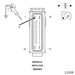 |
| 1. | Turn the ignition off. |
| 2. | Disconnect the ABS Module harness connector. |
| 3. | Using a 12-volt test light connected to 12-volts, probe the (A107) Fused B+ circuit. |
Does the test light illuminate brightly?
Yes
- Repair the (A107) Fused B(+) circuit for a short to ground.
- Perform the ABS VERIFICATION TEST. (Refer to 28 - DTC-Based Diagnostics/MODULE, Antilock Brake (ABS) - Standard Procedure).
No
-
Go To 5
5. CHECK THE (A107) FUSED B(+) CIRCUIT
| 1. | Turn the ignition off. |
| 2. | Visually inspect the (A107) Fused B(+) circuit in the wiring harness. |
| 3. | Look for any signs of intermittent short to ground. |
Is the wiring harness OK?
Yes
- Go To 6
No
- Repair the (A107) Fused B(+) circuit for a short to ground.
- Perform the ABS VERIFICATION TEST. (Refer to 28 - DTC-Based Diagnostics/MODULE, Antilock Brake (ABS) - Standard Procedure).
6. CHECK THE VOLTAGE ON THE (A107) FUSED B(+) CIRCUIT
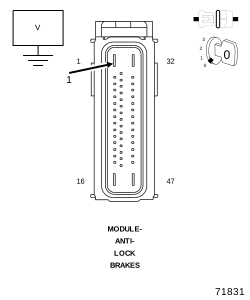 |
| 1. | Turn the ignition off. |
| 2. | Disconnect the ABS Module harness connector. |
| 3. | Measure the voltage of the (A107) Fused B(+) circuit in the Anti-Lock Brake Module harness connector. |
Is the voltage above 10 volts?
Yes
- Go To 7
No
- Repair the (A107) Fused B(+) circuit for an open.
-
Perform the ABS VERIFICATION TEST. (Refer to 28 - DTC-Based Diagnostics/MODULE, Antilock Brake (ABS)
- Standard Procedure).
7. CHECK THE (Z907) AND (Z917) GROUND CIRCUITS FOR AN OPEN
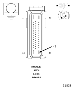 |
| 1. | Measure the resistance of the (Z907) and (Z917) Ground circuits between the Anti-Lock Brake Module harness connector and ground |
Is the resistance below 5.0 Ohms?
Yes
- Replace the ICU per service information.
- Perform the ABS VERIFICATION TEST. (Refer to 28 - DTC-Based Diagnostics/MODULE, Antilock Brake (ABS) - Standard Procedure).
No
- Repair the high resistance in the affected circuit.
-
Perform the ABS VERIFICATION TEST. (Refer to 28 - DTC-Based Diagnostics/MODULE, Antilock Brake (ABS)
- Standard Procedure).