C1090-ABS BRAKE LAMP CONTROL CIRCUIT LOW
For a complete wiring diagram, refer to the Wiring Information.
| NOTE: |
The Electronic Stability Control (ESC) may also be referred to as Electronic Stability Program (ESP) depending on the vehicle model year and configuration. Certain components may also reference ESP, ESC, or use the traction control symbol. |
-
When Monitored:
With the ignition on.
-
Set Condition:
When monitoring the Brake Lamp Activation Relay Control circuit the module detects a short to ground.
Possible Causes |
|---|
| (B401) BRAKE LAMP ACTIVATION RELAY CONTROL OPEN OR SHORTED TO GROUND |
| BLOWEN FUSE |
| BRAKE LAMP ACTIVATION RELAY |
| ANTI-LOCK BRAKE SYSTEM (ABS) MODULE |
1. CHECK FOR DTC C1090-ABS BRAKE LAMP CONTROL CIRCUIT LOW
| NOTE: | This DTC must be active for the results of this test to be valid. |
| 1. | Turn the ignition on. |
| 2. | With the scan tool, record and erase DTCs. |
| 3. | Start Engine. |
| 4. | Apply brake pedal firmly with at least 80 bar (1160 psi.) . |
| 5. | With the scan tool, read DTCs. |
Does the scan tool display: C1090-ABS BRAKE LAMP CONTROL CIRCUIT LOW?
Yes
- Go To 2
No
- Perform the ABS-INTERMITTENT CONDITION TEST. (Refer to 28 - DTC-Based Diagnostics/MODULE, Antilock Brake (ABS) - Standard Procedure).
2. CHECK CONNECTOR/TERMINAL FOR DAMAGE
| NOTE: | Check all terminals for broken, bent, pushed out, or corroded terminals. |
| 1. | Turn the ignition off. |
| 2. | Inspect the ABS Module harness connector and the Brake Lamp Activation Relay harness connector. |
Is the ABS Module or any of the connectors/terminals damaged?
Yes
- Repair as necessary.
- Perform the ABS VERIFICATION TEST. (Refer to 28 - DTC-Based Diagnostics/MODULE, Antilock Brake (ABS) - Standard Procedure).
No
- Go To 3
3. CHECK (B401) BRAKE LAMP ACTIVATION RELAY CONTROL SHORTED TO GROUND
| 1. | Turn the ignition off. |
| 2. | Disconnect the ABS Module harness connector. |
| 3. | Start the engine. |
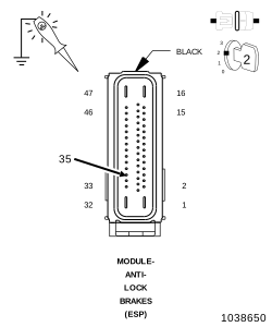
| 4. | Using a 12-volt test light connected to ground, probe the (B401) Brake Lamp Activation Relay Control Circuit at the ABS Module harness connector. |
Does the test light illuminate brightly?
Yes
- Replace the Anti-Lock Brake System (ABS) Module in accordance with the service information.
- Perform the ABS VERIFICATION TEST. (Refer to 28 - DTC-Based Diagnostics/MODULE, Antilock Brake (ABS) - Standard Procedure).
No
-
Go To 4
4. CHECK (F941) FUSED RUN/START RELAY OUTPUT
| 1. | Turn the ignition off. |
| 2. | Disconnect the Brake Lamp Activation Relay. |
| 3. | Start the engine. |
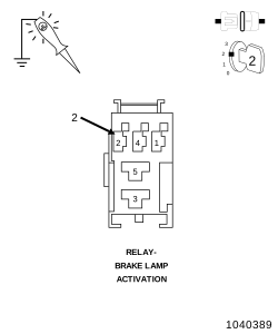
| 4. | Using a 12-volt test light connected to ground, probe the (F941) Fused Run/Start Relay Output Circuit at the Brake Lamp Activation Relay harness connector. |
Does the test light illuminate brightly?
Yes
- Go To 5
No
- Check for open Fuse, if ok repair open or short to ground in the (F941) Fused Run/Start Relay Output Circuit.
-
Perform the ABS VERIFICATION TEST. (Refer to 28 - DTC-Based Diagnostics/MODULE, Antilock Brake (ABS)
- Standard Procedure).
5. BRAKE LAMP ACTIVATION RELAY
| 1. | Turn the ignition off. |
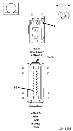
| 2. | Measure the resistance of the (B401) Brake Lamp Activation Relay Control Circuit between the Brake Lamp Activation relay and the ABS Module harness connector. |
Is the resistance 5 Ohms ?
Yes
- Replace the Brake Lamp Activation Relay in accordance with the Service Information.
- Perform the ABS VERIFICATION TEST. (Refer to 28 - DTC-Based Diagnostics/MODULE, Antilock Brake (ABS) - Standard Procedure).
No
- Repair open in the (B401) Brake Lamp Activation Relay Control circuit.
-
Perform the ABS VERIFICATION TEST. (Refer to 28 - DTC-Based Diagnostics/MODULE, Antilock Brake (ABS)
- Standard Procedure).