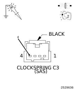
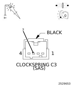
For a complete wiring diagram, refer to the Wiring Information.
NOTE:
The Electronic Stability Control (ESC) may also be referred to as Electronic Stability Program (ESP) depending on the vehicle model year and configuration. Certain components may also reference ESP, ESC, or use the traction control symbol.
When Monitored:
Continuous monitoring.
Set Condition:
When the Anti-Lock Brake System (ABS) Module detects a low voltage at the Steering Angle Sensor or Steering Angle Sensor failure.
Possible Causes
TERMINAL/CONNECTOR/WIRING HARNESS DAMAGE
(F943) FUSED B(+) CIRCUIT OPEN OR HIGH RESISTANCE
(Z910) GROUND CIRCUIT OPEN OR HIGH RESISTANCE
CLOCKSPRING (SAS)
1.
CHECK FOR A DTC C121A-STEERING ANGLE SENSOR NOT INITIALIZED
NOTE:
This DTC must be active for the results of this test to be valid.
1.
Turn the ignition on.
2.
With the scan tool, read and record DTCs.
3.
With the scan tool, read and record Environmental Data to help identify the conditions in which the DTC was set.
4.
With the scan tool, erase DTCs.
5.
Road test the vehicle over 30 km/h (19 mph) for at least 30 seconds.
6.
With the scan tool, read and record DTCs.
Does the scan tool display: C121A-STEERING ANGLE SENSOR NOT INITIALIZED?
2.
CHECK THE TERMINALS/CONNECTORS/WIRING HARNESS FOR DAMAGE
WARNING:
To avoid serious or fatal injury
on vehicles equipped with airbags, disable the Supplemental Restraint
System (SRS) before attempting any steering wheel, steering column,
airbag, seat belt tensioner, impact sensor, or instrument panel component
diagnosis or service. Disconnect and isolate the battery negative
(ground) cable, then wait two minutes for the system capacitor to
discharge before performing further diagnosis or service. This is
the only sure way to disable the SRS. Failure to take the proper precautions
could result in accidental airbag deployment.
NOTE:
Proper Steering Angle Sensor installation is crucial for proper operation.
1.
Check the Clockspring / Steering Angle Sensor installation.
2.
Check all related wiring for bruised, chafed, pierced, or partially broken wires.
3.
Check all related connectors for broken, bent, pushed out, or corroded terminals.