Home › 28 - DTC-Based Diagnostics › MODULE, Powertrain Control (PCM), 2.8L VM › P0132-O2 SENSOR 1/1 CIRCUIT HIGHP0132-O2 SENSOR 1/1 CIRCUIT HIGH
Special Tools: Click to display a list of tools used in this procedure
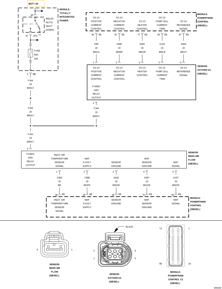
For a complete wiring diagram, refer to the Wiring Information .
Possible Causes
(K892) O2 SENSOR 1/1 SIGNAL CIRCUIT SHORTED TO VOLTAGE
MASS AIRFLOW SENSOR
INTAKE SYSTEM LEAK OR RESTRICTION
EXHAUST SYSTEM LEAK OR RESTRICTION
EGR SYSTEM LEAK
EXCESSIVE FUELING CONDITION
OXYGEN SENSOR
POWERTRAIN CONTROL MODULE (PCM)
Always perform the Pre-Diagnostic Troubleshooting procedure before proceeding. (Refer to 28 - DTC-Based Diagnostics/MODULE, Powertrain Control (PCM)
- Standard Procedure) .
1.
DTC IS ACTIVE
NOTE:
If there are any Mass
Airflow Sensor or Fuel Injector DTCs present, diagnose those DTCs
before proceeding with this test procedure.
1.
Ignition on, engine
not running.
2.
With the scan tool,
erase DTCs in the PCM.
4.
Allow the engine
to reach normal operating temperature.
5.
Test drive the
vehicle under several different driving conditions.
6.
With the scan tool,
select View DTCs.
Is the
status Active for this DTC? Yes
No
2.
CHECK THE (K892)
O2 SENSOR 1/1 SIGNAL CIRCUIT FOR A SHORT TO VOLTAGE
1.
Turn the ignition
off.
2.
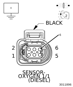
Disconnect the
Oxygen Sensor harness connector.
3.
Disconnect the
PCM C1 harness connector.
4.
Remove the ASD
Relay from the TIPM.
5.
Connect a jumper
wire between cavity 30 and cavity 87 of the ASD Relay Connector.
7.
Measure the voltage
of the (K892) O2 Sensor 1/1 Signal circuit at the Oxygen Sensor harness
connector.
Is there
any voltage present? Yes
No
3.
CHECK THE AIR
FILTER
1.
Turn the ignition
off.
2.
Remove the jumper
wire and install the ASD Relay.
3.
Remove and inspect
the Air Filter for soiling or excessive dirt and debris which may
cause air flow restriction.
4.
Check the Inlet
Tube for signs of excessive dirt, snow, or ice restricting airflow
into the Air Filter Box.
Were
any problems found? Yes
No
4.
CHECK FOR INTAKE
SYSTEM RESTRICTIONS
1.
Turn the ignition
off.
2.
Inspect all air
intake, crankcase vent and Turbocharger related hoses/tubes and connections.
3.
Inspect the Charge
Air Cooler inlet and outlet hoses/tubes and connections.
4.
Inspect the EGR
Air Flow Control Valve to ensure the valve is not stuck in the closed
position.
Were
any problems found? Yes
No
5.
CHECK FOR INTAKE
SYSTEM AIR LEAKS
1.
Remove the Crankcase
Vent Heater.
2.
Remove the Mass
Air Flow Sensor from the Turbocharger Inlet Tube.
3.
Seal off and/or
plug the Turbocharger Inlet Tube where the MAF sensor was removed.
4.
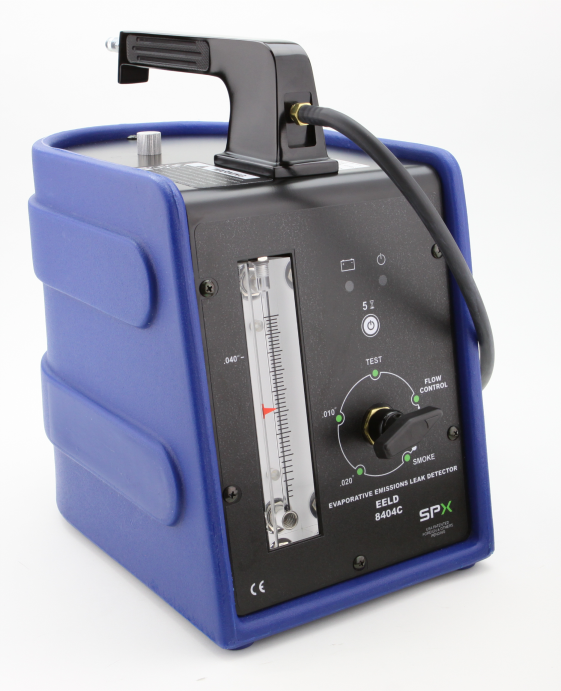
Connect the Evaporative
Emissions Leak Detector
Kit, EELD And Accessory 8404C
to the Crankcase
Vent Heater port in the intake duct and begin injecting smoke into
the intake system.
5.
Observe all intake
system components for evidence of smoke leakage.
Is there
evidence of smoke leakage? Yes
No
6.
CHECK THE EXHAUST
SYSTEM FOR LEAKS OR RESTRICTIONS
1.
Visually inspect
the entire exhaust system for damage, leaks or restrictions.
Were
any problems found? Yes
No
7.
CHECK THE FUEL
DELIVERY SYSTEM
Were
any problems found? Yes
No
8.
OXYGEN SENSOR
1.
Reconnect the PCM
C1 harness connector.
2.
Replace the Oxygen
Sensor in accordance with the service information.
4.
Allow the engine
to reach normal operating temperature.
5.
Monitor the scan
tool for at least two minutes.
6.
With the scan tool,
select View DTCs.
Is the
status Active for this DTC? Yes
No
9.
POWERTRAIN CONTROL
MODULE
1.
Using the wiring
diagram/schematic as a guide, inspect the wiring and connectors between
the Oxygen Sensor and the Powertrain Control Module.
2.
Look for any chafed,
pierced, pinched, or partially broken wires.
3.
Look for broken,
bent, pushed out or corroded terminals.
4.
Monitor the scan
tool data relative to this circuit and wiggle test the wiring and
connectors.
5.
Look for the data
to change or for the DTC to reset during the wiggle test.
6.
Perform any Technical
Service Bulletins that may apply.
Were
any problems found? Yes
No