P034A-CRANKSHAFT POSITION SENSOR - CRANKSHAFT START POSITION INCORRECT
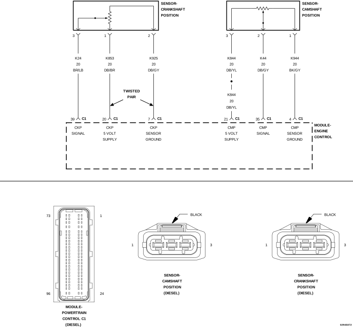 |
For a complete wiring diagram, refer to the Wiring Information.
Theory of Operation
The Crankshaft Position (CKP) Sensor is a hall effect type sensor. The sensor produces a 5 Volt digital signal (square wave). The PCM provides a 5-Volt supply, 5-Volt Sensor Signal and ground to the CKP Sensor. The sensor is positioned opposite a magnetic ring at the rear of the crankshaft. The magnetic ring contains internal magnetic strips (electric teeth) that act on the hall-effect switch causing the digital switching of the sensor signal from high (5 Volts) to low (0 Volts).
-
When Monitored:
With the engine cranking or running.
-
Set Condition:
The Powertrain Control Module (PCM) does not receive a signal from the Crankshaft Position Sensor (CKP) when the Camshaft Position Sensor (CMP) indicates engine rpm.
Possible Causes |
|---|
| (K853) CKP SENSOR 5-VOLT SUPPLY CIRCUIT OPEN/HIGH RESISTANCE |
| (K24) CKP SENSOR SIGNAL CIRCUIT SHORTED TO VOLTAGE |
| (K925) CKP SENSOR GROUND CIRCUIT OPEN/HIGH RESISTANCE |
| (K24) CKP SENSOR SIGNAL CIRCUIT OPEN/HIGH RESISTANCE |
| (K853) CKP SENSOR 5-VOLT SUPPLY CIRCUIT SHORTED TO GROUND |
| (K24) CKP SENSOR SIGNAL CIRCUIT SHORTED TO GROUND |
| (K925) CKP SENSOR GROUND CIRCUIT OPEN/HIGH RESISTANCE |
| (K853) CKP SENSOR 5-VOLT SUPPLY CIRCUIT SHORTED TO THE (K925) CKP SENSOR GROUND CIRCUIT |
| (K24) CKP SENSOR SIGNAL CIRCUIT SHORTED TO THE (K925) CKP SENSOR GROUND CIRCUIT |
| CRANKSHAFT POSITION SENSOR |
| POWERTRAIN CONTROL MODULE (PCM) |
Always perform the Pre-Diagnostic Troubleshooting procedure before proceeding. (Refer to 28 - DTC-Based Diagnostics/MODULE, Powertrain Control (PCM) - Standard Procedure).
| NOTE: | If any Sensor Reference DTCs are present, perform the applicable diagnostic procedure before continuing with this test. |
| NOTE: | The Timing Belt/Chain must be correctly installed and operational before diagnosis can be made. Refer to the service information to ensure the timing belt is properly installed. |
| NOTE: | If the PCM detects and stores a DTC, the PCM also stores the engine/vehicle operating conditions under which the DTC was set. Some of these conditions are displayed on the scan tool at the same time the DTC is displayed. |
| NOTE: | Before erasing stored DTCs, record these conditions. Attempting to duplicate these conditions may assist when checking for an active DTC. |
| 1. | Turn the ignition on. |
| 2. | With the scan tool, erase the PCM DTCs. |
| 3. | Attempt to start the engine cranking the engine for at least 7 seconds. |
| 4. | With the scan tool, read the PCM DTCs. |
Does the scan tool display this DTC?
Yes
- Go To 3
No
- Go To 2
| 1. | Turn the ignition on. |
| 2. | With the scan tool, erase the PCM DTCs. |
| 3. | Test drive the vehicle. |
| 4. | With the scan tool, read the PCM DTCs. |
Does the scan tool display this DTC?
Yes
- Go To 3
No
- Perform the INTERMITTENT DTC diagnostic procedure. (Refer to 28 - DTC-Based Diagnostics/MODULE, Powertrain Control (PCM) - Standard Procedure).
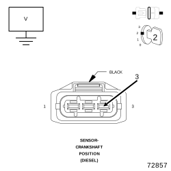
3. CHECK THE (K24) CRANKSHAFT POSITION SENSOR SIGNAL CIRCUIT
 |
| 1. | Turn the ignition off. |
| 2. | Disconnect the Crankshaft Position Sensor harness connector. |
| 3. | Turn the ignition on. |
| 4. | Measure the voltage of the (K24) CKP Sensor Signal circuit at the CKP Sensor harness connector. |
Select the appropriate voltage reading.
Voltage is above 5.2 Volts
- Go To 4
Voltage is between 4.8 and 5.2 Volts
- Go To 5
Voltage is below 4.8 Volts
-
Go To 11
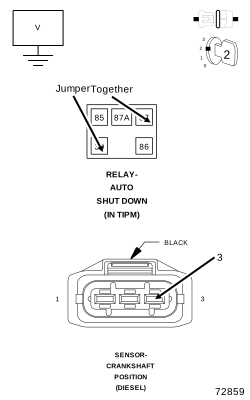
4. CHECK THE (K24) CRANKSHAFT POSITION SENSOR SIGNAL CIRCUIT FOR A SHORT TO VOLTAGE
 |
| 1. | Turn the ignition off. |
| 2. | Disconnect the PCM harness connectors. |
| 3. | Remove the ASD Relay. |
| 4. | Connect a jumper wire between cavity 30 and cavity 87 of the ASD Relay connector. |
| 5. | Turn the ignition on. |
| 6. | Measure the voltage of the (K24) CKP Sensor Signal circuit at the CKP Sensor harness connector. |
Is the voltage below 1.0 Volt?
Yes
- Replace and program the Powertrain Control Module in accordance with the service information.
- Perform the PCM VERIFICATION TEST. (Refer to 28 - DTC-Based Diagnostics/MODULE, Powertrain Control (PCM) - Standard Procedure).
No
- Repair the (K24) Crankshaft Position Sensor Signal circuit for a short to voltage.
-
Perform the PCM VERIFICATION TEST. (Refer to 28 - DTC-Based Diagnostics/MODULE, Powertrain Control (PCM)
- Standard Procedure).
5. CHECK THE (K853) CRANKSHAFT POSITION SENSOR 5-VOLT SUPPLY CIRCUIT
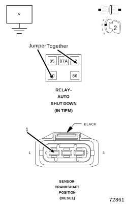 |
| 1. | Measure the voltage of the (K853) CKP Sensor 5-Volt Supply circuit at the CKP Sensor harness connector. |
Select the appropriate voltage reading.
Voltage is above 5.2 Volts
- Repair the (K853) CKP 5-Volt Supply circuit for a short to voltage.
- Perform the PCM VERIFICATION TEST. (Refer to 28 - DTC-Based Diagnostics/MODULE, Powertrain Control (PCM) - Standard Procedure).
Voltage is between 4.8 and 5.2 Volts
- Go To 6
Voltage is below 4.8 Volts
-
Go To 8
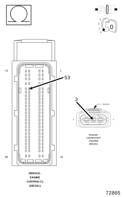
6. CHECK THE (K925) CRANKSHAFT POSITION SENSOR GROUND CIRCUIT FOR AN OPEN/HIGH RESISTANCE
 |
| 1. | Turn the ignition off. |
| 2. | Disconnect the PCM harness connectors. |
| 3. | Measure the resistance of the (K925) CKP Sensor Ground circuit between the CKP Sensor harness connector and the PCM harness connector. |
Is the resistance below 5.0 Ohms?
Yes
- Go To 7
No
- Repair the (K925) CKP Sensor Ground circuit for an open or high resistance.
-
Perform the PCM VERIFICATION TEST. (Refer to 28 - DTC-Based Diagnostics/MODULE, Powertrain Control (PCM)
- Standard Procedure).
7. DAMAGED CRANKSHAFT POSITION SENSOR OR CRANKSHAFT
| 1. | Turn the ignition off. |
| 2. | Remove the CKP Sensor. |
| 3. | Inspect the CKP Sensor for conditions such as loose mounting screws, damage, or cracks. |
| 4. | Inspect the Crankshaft magnetic ring for conditions such as damage, or debris. |
Is there any evidence of these conditions?
Yes
- Replace and program the PCM in accordance with the service information.
- Perform the PCM VERIFICATION TEST. (Refer to 28 - DTC-Based Diagnostics/MODULE, Powertrain Control (PCM) - Standard Procedure).
No
- Replace the Crankshaft Position Sensor in accordance with the Service Information.
- Perform the PCM VERIFICATION TEST. (Refer to 28 - DTC-Based Diagnostics/MODULE, Powertrain Control (PCM) - Standard Procedure).
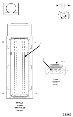
8. CHECK THE (K853) CRANKSHAFT POSITION SENSOR 5-VOLT SUPPLY CIRCUIT FOR AN OPEN/HIGH RESISTANCE
 |
| 1. | Turn the ignition off. |
| 2. | Disconnect the PCM C1 harness connector. |
| 3. | Measure the resistance of the (K853) CKP Sensor 5-Volt Supply circuit between the PCM C1 harness connector and the CKP Sensor harness connector. |
Is the resistance below 5.0 Ohms?
Yes
- Go To 9
No
- Repair the (K853) CKP Sensor 5-Volt Supply circuit for an open or high resistance.
-
Perform the PCM VERIFICATION TEST. (Refer to 28 - DTC-Based Diagnostics/MODULE, Powertrain Control (PCM)
- Standard Procedure).
9. CHECK THE (K853) CRANKSHAFT POSITION SENSOR 5-VOLT SUPPLY CIRCUIT FOR A SHORT TO GROUND
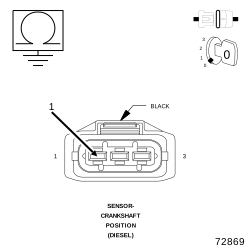 |
| 1. | Measure the resistance between ground and the (K853) CKP Sensor 5-Volt Supply circuit at the CKP Sensor harness connector. |
Is the resistance above 10k Ohms?
Yes
- Go To 10
No
- Repair the (K853) CKP Sensor 5-Volt Supply circuit for a short to ground.
-
Perform the PCM VERIFICATION TEST. (Refer to 28 - DTC-Based Diagnostics/MODULE, Powertrain Control (PCM)
- Standard Procedure).
10. CHECK FOR THE (K853) CRANKSHAFT POSITION SENSOR 5-VOLT SUPPLY CIRCUIT SHORTED TO THE (K925) CKP SENSOR GROUND CIRCUIT
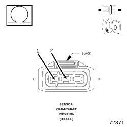 |
| 1. | Measure the resistance between the (K853) CKP Sensor 5-Volt Supply circuit and the (K925) CKP Sensor Ground circuit at the CKP Sensor harness connector. |
Is the resistance above 10k Ohms?
Yes
- Replace and program the Powertrain Control Module in accordance with the service information.
- Perform the PCM VERIFICATION TEST. (Refer to 28 - DTC-Based Diagnostics/MODULE, Powertrain Control (PCM) - Standard Procedure).
No
- Repair the (K853) CKP Sensor 5-Volt Supply circuit for a short to the (K925) CKP Sensor Ground circuit.
-
Perform the PCM VERIFICATION TEST. (Refer to 28 - DTC-Based Diagnostics/MODULE, Powertrain Control (PCM)
- Standard Procedure).
11. CHECK THE (K24) CRANKSHAFT POSITION SENSOR SIGNAL CIRCUIT FOR AN OPEN/HIGH RESISTANCE
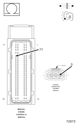 |
| 1. | Disconnect the PCM C1 harness connector. |
| 2. | Measure the resistance of the (K24) CKP Sensor Signal circuit between the PCM C1 harness connector and the CKP Sensor harness connector. |
Is the resistance below 5.0 Ohms?
Yes
- Go To 12
No
- Repair the (K24) CKP Sensor Signal circuit for an open or high resistance
-
Perform the PCM VERIFICATION TEST. (Refer to 28 - DTC-Based Diagnostics/MODULE, Powertrain Control (PCM)
- Standard Procedure).
12. CHECK THE (K24) CRANKSHAFT POSITION SENSOR SIGNAL CIRCUIT FOR A SHORT TO GROUND
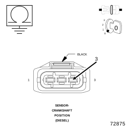 |
| 1. | Measure the resistance between ground and the (K24) CKP Sensor Signal circuit at the CKP Sensor harness connector. |
Is the resistance above 10k Ohms?
Yes
- Go To 13
No
- Repair the (K24) CKP Sensor Signal circuit for a short to ground.
-
Perform the PCM VERIFICATION TEST. (Refer to 28 - DTC-Based Diagnostics/MODULE, Powertrain Control (PCM)
- Standard Procedure).
13. CHECK FOR THE (K24) CRANKSHAFT POSITION SENSOR SIGNAL CIRCUIT SHORTED TO THE (K925) CKP SENSOR GROUND CIRCUIT
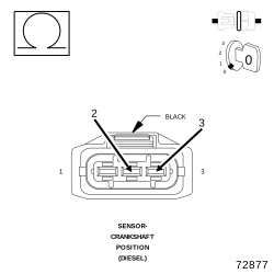 |
| 1. | Measure the resistance between the (K24) CKP Sensor Signal circuit and the (K925) CKP Sensor Ground circuit at the CKP Sensor harness connector. |
Is the resistance above 10k Ohms?
Yes
- Replace and program the Powertrain Control Module in accordance with the service information.
- Perform the PCM VERIFICATION TEST. (Refer to 28 - DTC-Based Diagnostics/MODULE, Powertrain Control (PCM) - Standard Procedure).
No
- Repair the (K24) CKP Sensor Signal circuit for a short to the (K925) CKP Sensor Ground circuit.
-
Perform the PCM VERIFICATION TEST. (Refer to 28 - DTC-Based Diagnostics/MODULE, Powertrain Control (PCM)
- Standard Procedure).