P0401-EGR FLOW INSUFFICIENT DETECTED
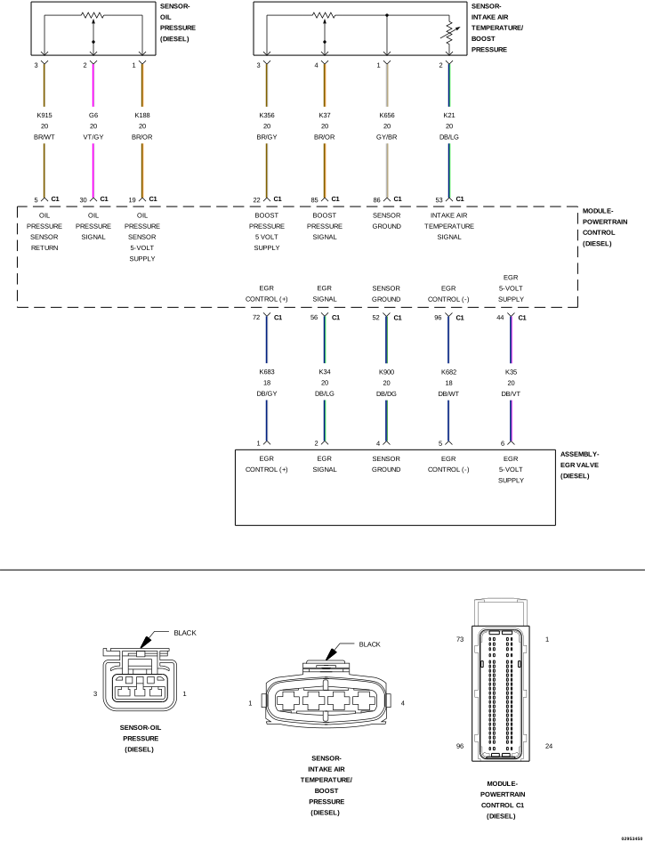 |
For a complete wiring diagram, refer to the Wiring Information.
Theory of Operation
The EGR Airflow Control Valve is a pulse width modulated output, controlled by the Powertrain Control Module (PCM). The EGR Airflow Control Valve is used to control the ratio of fresh air flow to EGR gas air flow. The PCM monitors this ratio with the Mass Air Flow Sensor. The Mass Air Flow Sensor feedback is very prominent in determining the position of the EGR Airflow Control Valve. If the Mass Air Flow Sensor feedback does not match what the PCM is expecting to see when EGR air flow is requested, it can effect the operation of the EGR Valve and the EGR Airflow Control Valve. This can occur if the Mass Air Flow Sensor feedback is faulty or inaccurate, even if no DTCs are actively set. The EGR system and Diesel Particulate Filter regeneration is disabled when the fault is active.
-
When Monitored:
With the engine running.
-
Set Condition:
The Powertrain Control Module (PCM) detects EGR flow is less than the requested flow for five seconds.
Possible Causes |
|---|
| AIR FILTER |
| INTAKE SYSTEM AIR LEAKS OR RESTRICTIONS |
| EGR AIR FLOW CONTROL VALVE |
| EGR COOLER AND TUBES RESTRICTED |
| EGR VALVE |
| NOTE: | If the PCM detects and stores a DTC, the PCM also stores the operating conditions under which the DTC was set. Some of these conditions are displayed on the scan tool at the same time the DTC is displayed. Before erasing stored DTCs, record these conditions. Attempting to duplicate these conditions may assist when checking for an active DTC. |
| NOTE: | If there are any Mass Air Flow DTCs present, diagnose the MAF DTCs before continuing EGR diagnostics. |
| 1. | Turn the ignition on. |
| 2. | With the scan tool, erase PCM DTCs. |
| 3. | Test drive the vehicle and monitor the scan tool for PCM DTCs. |
Did this DTC return?
Yes
- Go To 2
No
- Perform the INTERMITTENT DTC diagnostic procedure. (Refer to 28 - DTC-Based Diagnostics/MODULE, Powertrain Control (PCM) - Standard Procedure).
| 1. | Turn the ignition off. |
| 2. | Remove and inspect the Air Filter for soiling or excessive dirt and debris which may cause air flow restriction. |
Were any of these problems found?
Yes
- Replace the Air Filter element in accordance with the service information.
- Perform the PCM VERIFICATION TEST. (Refer to 28 - DTC-Based Diagnostics/MODULE, Powertrain Control (PCM) - Standard Procedure).
No
- Go To 3
| 1. | Visually inspect the fresh air inlet tube for a blockage due to snow, ice or dirt buildup. |
| 2. | Visually inspect the intake system, exhaust system and related tubes and connections. |
| NOTE: | Inspect all air intake, crankcase vent and Turbocharger related tubes for damage, restriction or poor connection. Any of these conditions can cause this DTC to set. |
| NOTE: | Inspect the exhaust system and related tubes for damage, restriction or poor connection. Any of these conditions can cause this DTC to set. |
Were any problems found?
Yes
- Repair or replace as necessary.
- Perform the PCM VERIFICATION TEST. (Refer to 28 - DTC-Based Diagnostics/MODULE, Powertrain Control (PCM) - Standard Procedure).
No
- Go To 4
| 1. | Remove the Inlet Pressure Sensor. |
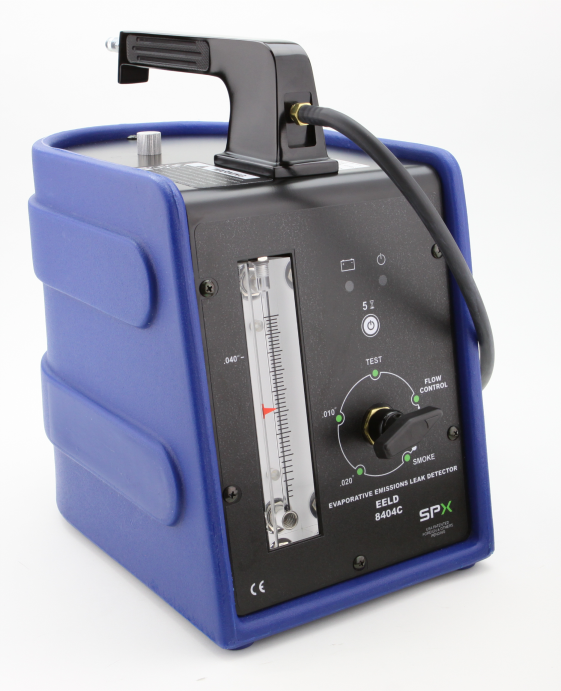
| 2. | Connect Evaporative Emissions Leak Detector Kit, EELD And Accessory 8404C to the Inlet Pressure Sensor port in the intake duct and begin injecting smoke into the intake system. |
| 3. | Observe all intake system components for evidence of smoke leakage. |
Is there evidence of a leak?
Yes
- Repair or replace as necessary.
- Perform the PCM VERIFICATION TEST. (Refer to 28 - DTC-Based Diagnostics/MODULE, Powertrain Control (PCM) - Standard Procedure).
No
- Go To 5
5. CHECK THE EGR AIR FLOW CONTROL VALVE
| 1. | Disconnect the air tube at the inlet port of the EGR Air Flow Control Valve. |
| 2. | Use a mirror to observe the motion of the EGR Air Flow Control Valve. |
| 3. | Turn the ignition on. |
| 4. | The EGR Air Flow Control Valve should open completely without binding with the ignition on. |
| NOTE: | Cycle the ignition on and off several times while observing the operation of the valve. |
Did the EGR Air Flow Control Valve operate correctly and without binding?
Yes
- Go To 6
No
- Replace the EGR Air Flow Control Valve in accordance with the service information.
- Perform the PCM VERIFICATION TEST. (Refer to 28 - DTC-Based Diagnostics/MODULE, Powertrain Control (PCM) - Standard Procedure).
6. CHECK THE EGR COOLER AND TUBES
| 1. | Turn the ignition off. |
| 2. | Gain access to and inspect the EGR Cooler and both tubes that connect to the EGR Cooler. Check tubes and cooler for damage, leaks, excessive soot build up and other problems that could restrict or prevent proper exhaust gas flow. |
| NOTE: | Compressed air (at low pressure) can be applied to the lower port of the EGR Cooler. When applying compressed air check for air to flow through cooler and out the upper port. Always wear safety glasses when working with compressed air. |
Were any problems found?
Yes
- Clean or replace the EGR Cooler or tubes as necessary.
- Perform the PCM VERIFICATION TEST. (Refer to 28 - DTC-Based Diagnostics/MODULE, Powertrain Control (PCM) - Standard Procedure).
No
- Replace the EGR Valve in accordance with the service information.
- Perform the PCM VERIFICATION TEST. (Refer to 28 - DTC-Based Diagnostics/MODULE, Powertrain Control (PCM) - Standard Procedure).