P0460-FUEL LEVEL SENSOR 1
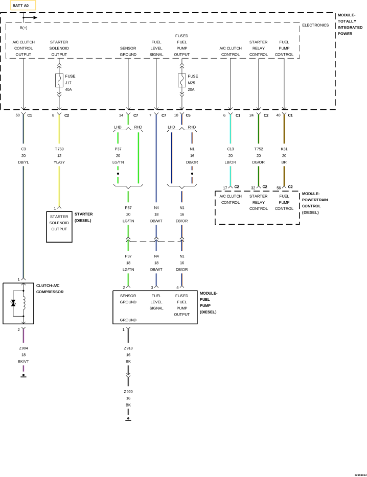 |
For a complete wiring diagram, refer to wiring information.
Theory of Operation
The fuel level rationality will set a fault for a fuel level reading that does not change over an accumulated mileage threshold to keep stuck high or stuck low fuel levels from disabling OBD monitors.The power up test looks to see a large enough fuel level voltage change from the last key-off to the following engine run. The engine run test looks to see a fuel level voltage change over an accumulated mileage.
-
When Monitored:
TEST No.1: With the ignition on, the fuel level is compared to the previous key down after a 20 second delay. TEST No.2: The Totally Integrated Power Module (TIPM) monitors the fuel level at ignition on.
-
Set Condition:
TEST No.1: If the TIPM does not see a difference in fuel level of greater than 0.1 Volt the test will fail. TEST No.2: If the TIPM does not see a change in the fuel level of .1765 over a set amount of miles the test will fail. Two trip fault. Three good trips to turn off the MIL.
Possible Causes |
|---|
| (N4) FUEL LEVEL SENSOR SIGNAL CIRCUIT OPEN/HIGH RESISTANCE |
| (N4) FUEL LEVEL SENSOR SIGNAL CIRCUIT SHORTED TO GROUND |
| (Z920) FUEL LEVEL SENSOR GROUND CIRCUIT OPEN/HIGH RESISTANCE |
| FUEL TANK |
| FUEL LEVEL SENSOR |
Always perform the Pre-Diagnostic Troubleshooting procedure before proceeding. (Refer to 28 - DTC-Based Diagnostics/MODULE, Powertrain Control (PCM) - Standard Procedure).
| NOTE: | Diagnose any CAN - C or CAN - B Communication DTCs before continuing. |
| 1. | With a scan tool, select View DTCs and record the related Freeze Frame data. |
| 2. | With a scan tool, erase the DTCs. |
| 3. | Start the engine. |
| 4. | Allow the engine to reach normal operating temperature. |
| 5. | With a scan tool, check for active DTCs. |
Is the DTC Active or Pending at this time?
Yes
- Go To 2
No
- Perform the INTERMITTENT CONDITION diagnostic procedure. (Refer to 28 - DTC-Based Diagnostics/MODULE, Powertrain Control (PCM) - Standard Procedure).
| 1. | Turn the ignition off. |
| 2. | Visually inspect the Fuel Tank for damage that may restrict the Fuel Sending Unit float from moving. |
Was any damage found?
Yes
- Go To 3
No
- Replace the Fuel Tank in accordance with the service information.
- Perform the PCM VERIFICATION TEST. (Refer to 28 - DTC-Based Diagnostics/MODULE, Powertrain Control (PCM) - Standard Procedure).
3. CHECK THE (N4) FUEL LEVEL SENSOR SIGNAL CIRCUIT FOR AN OPEN/HIGH RESISTANCE
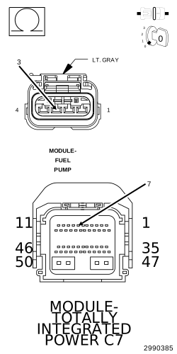 |
| 1. | Disconnect the Fuel Pump Module harness connector. |
| 2. | Disconnect the TIPM C7 harness connector. |
| 3. | Measure the resistance of the (N4) Fuel Level Sensor Signal circuit between the Fuel Pump Module harness connector and the TIPM C7 harness connector. |
Is the resistance below 5.0 Ohms?
Yes
- Go To 4
No
- Repair the (N4) Fuel Level Sensor Signal circuit for an open or high resistance.
-
Perform the PCM VERIFICATION TEST. (Refer to 28 - DTC-Based Diagnostics/MODULE, Powertrain Control (PCM)
- Standard Procedure).
4. CHECK THE (N4) FUEL LEVEL SENSOR SIGNAL CIRCUIT FOR A SHORT TO GROUND
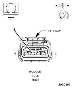 |
| 1. | Measure the resistance between ground and the (N4) Fuel Level Sensor Signal circuit at the Fuel Pump Module harness connector. |
Is the resistance below 10k Ohms?
Yes
- Repair the (N4) Fuel Level Sensor Signal circuit for a short to ground.
- Perform the PCM VERIFICATION TEST. (Refer to 28 - DTC-Based Diagnostics/MODULE, Powertrain Control (PCM) - Standard Procedure).
No
-
Go To 5
5. CHECK THE (Z920) FUEL LEVEL SENSOR GROUND CIRCUIT FOR AN OPEN/HIGH RESISTANCE
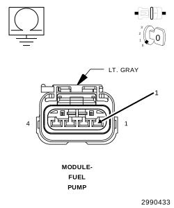 |
| 1. | Measure the resistance between a good chassis ground and the (K900) Fuel Level Sensor Ground circuit at the Fuel Pump Module harness connector. |
Is the resistance below 5.0 Ohms?
Yes
- Go To 6
No
- Repair the (K91) Fuel Level Sensor Ground circuit for an open or high resistance.
-
Perform the PCM VERIFICATION TEST. (Refer to 28 - DTC-Based Diagnostics/MODULE, Powertrain Control (PCM)
- Standard Procedure).
6. INTERNAL INSPECTION OF THE FUEL TANK
| 1. | Remove the Fuel Tank in accordance with the service information. |
| 2. | Remove the Fuel Pump Module from the tank. |
| 3. | Visually inspect the inside of the Fuel Tank for any obstructions or deformities. |
| 4. | Inspect the Fuel Pump Module Float arm for damage. |
Were any problems found?
Yes
- Repair or replace as necessary.
- Perform the PCM VERIFICATION TEST. (Refer to 28 - DTC-Based Diagnostics/MODULE, Powertrain Control (PCM) - Standard Procedure).
No
- Go To 7
If there are no possible causes remaining, view repair.
Repair
- Verify that there is good pin to terminal contact at the Fuel Pump Module and the Powertrain Control Module connectors. Replace the Fuel Level Sensor if no problems were found at the connectors.
- Perform the PCM VERIFICATION TEST. (Refer to 28 - DTC-Based Diagnostics/MODULE, Powertrain Control (PCM) - Standard Procedure).