P064C-GLOW PLUG CONTROL CIRCUIT MODULE 1
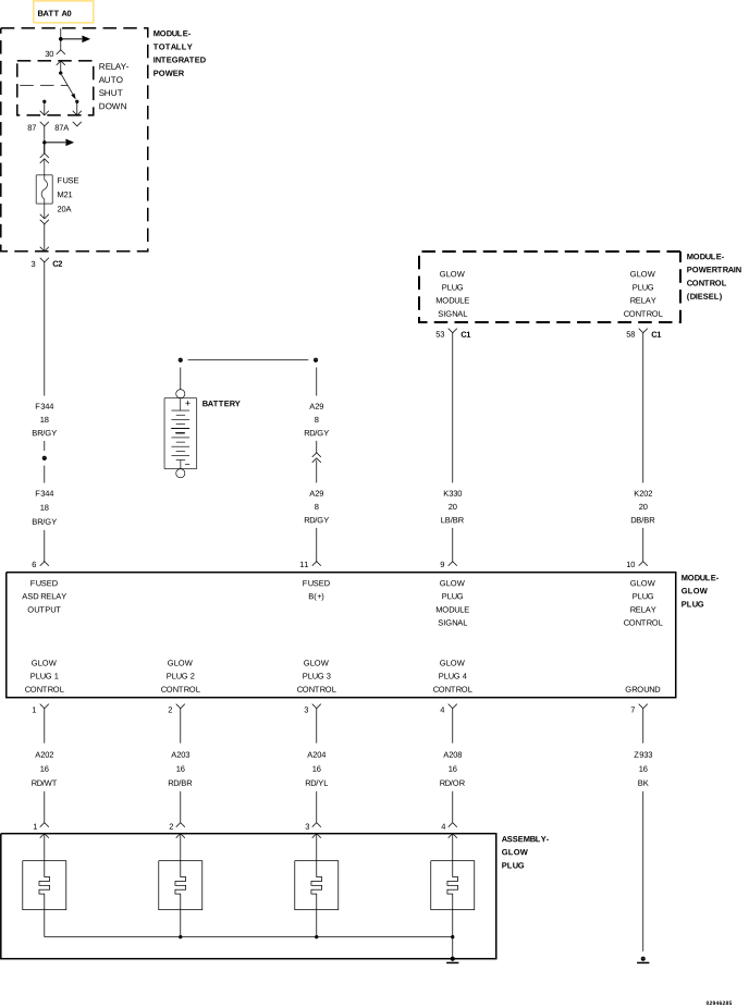 |
For a complete wiring diagram, refer to the Wiring Information.
Theory of Operation
The Glow Plug Module has the appearance of a large relay and is located next to the battery.The Glow Plug Module receives a signal from the Powertrain Control Module (PCM) to activate the Glow Plugs. The Glow Plug Module supplies power to the Glow Plugs and a ground path is provided through the body of the Glow Plugs. The Glow Plug Module communicates with the PCM over the (K330) Glow Plug Module Control circuit.
-
When Monitored:
Continuously with the ignition on and the Glow Plugs commanded on.
-
Set Condition:
The PCM receives and internal error failure from the Glow Plug Module 50 consecutive times.
Possible Causes |
|---|
| GLOW PLUG CONTROL MODULE |
Always perform the Pre-Diagnostic Troubleshooting procedure before proceeding. (Refer to 28 - DTC-Based Diagnostics/MODULE, Powertrain Control (PCM) - Standard Procedure).
DTC IS ACTIVE
| 1. | Ignition on, engine not running. |
| 2. | With the scan tool, select View DTCs. |
Is the status Active for this DTC?
Yes
- Replace and program the Glow Plug Control Module in accordance with the service information.
- Perform the PCM VERIFICATION TEST. (Refer to 28 - DTC-Based Diagnostics/MODULE, Powertrain Control (PCM) - Standard Procedure).
No
- Perform the INTERMITTENT DTC diagnostic procedure. (Refer to 28 - DTC-Based Diagnostics/MODULE, Powertrain Control (PCM) - Standard Procedure).