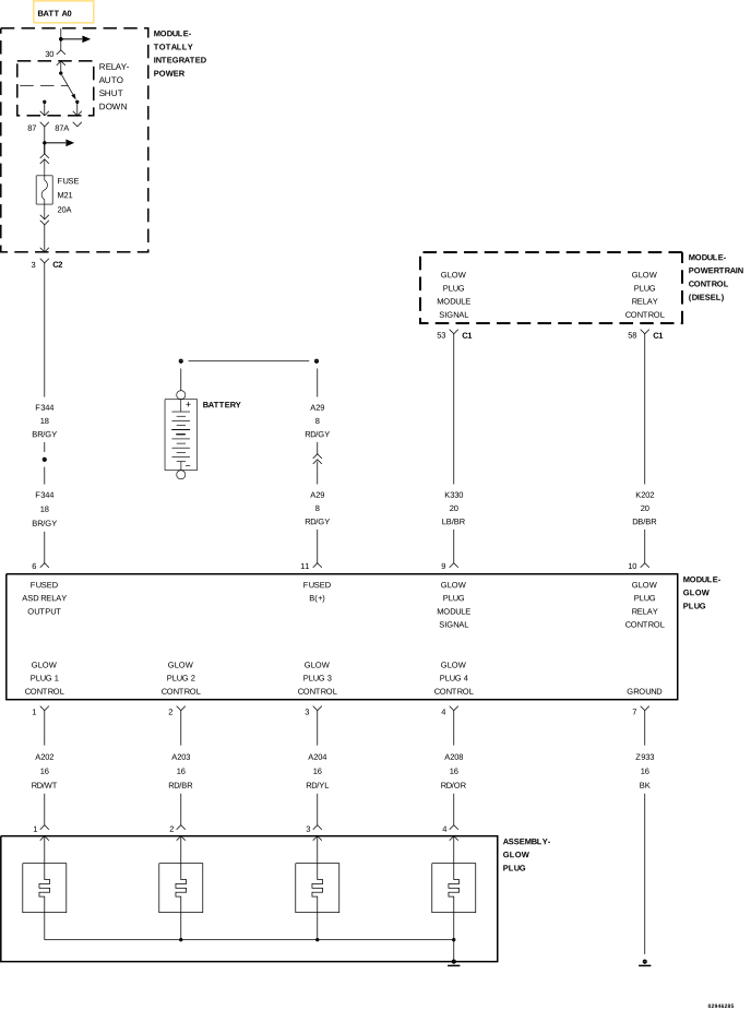
For a complete wiring diagram, refer to the Wiring Information.
Theory of Operation
The Glow Plug Module has the appearance of a large relay and is located next to the battery. The Glow Plug Module receives a signal from the Powertrain Control Module (PCM) to activate the Glow Plugs. The Glow Plug Module supplies power to the Glow Plugs and a ground path is provided through the body of the Glow Plugs. The Glow Plug Module communicates with the PCM over the (K330) Glow Plug Module Control circuit.
When Monitored:
Continuously with the ignition on and the Glow Plugs commanded on.
Set Condition:
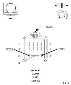
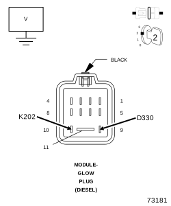
The PCM detects a malfunction on the (D330) Glow Plug Module Signal or (K202) Glow Plug Module Control circuit.
Possible Causes
(K202) GLOW PLUG MODULE CONTROL CIRCUIT SHORTED TO VOLTAGE
(D330) GLOW PLUG MODULE SIGNAL CIRCUIT SHORTED TO VOLTAGE
(K202) GLOW PLUG MODULE CONTROL CIRCUIT SHORTED TO GROUND
(D330) GLOW PLUG MODULE SIGNAL CIRCUIT SHORTED TO GROUND
(K202) GLOW PLUG MODULE CONTROL CIRCUIT OPEN/HIGH RESISTANCE
(D330) GLOW PLUG MODULE SIGNAL CIRCUIT OPEN/HIGH RESISTANCE
GLOW PLUG MODULE
POWERTRAIN CONTROL MODULE
1.
CHECK FOR ACTIVE DTC
NOTE:
If the PCM detects and stores a DTC, the PCM also stores the engine/vehicle operating conditions under which the DTC was set. Some of these conditions are displayed on the scan tool at the same time the DTC is displayed.
NOTE:
Before erasing stored DTCs, record these conditions. Attempting to duplicate these conditions may assist when checking for an active DTC.
1.
Turn the ignition on.
2.
With the scan tool, erase PCM DTCs.
3.
Perform several engine run cycles, turning the ignition off for at least 20 seconds between each engine run cycle.
4.
Turn the ignition on and wait at least 90 seconds.