P2009-INTAKE MANIFOLD RUNNER (SWIRL) CONTROL CIRCUIT LOW - BANK 1
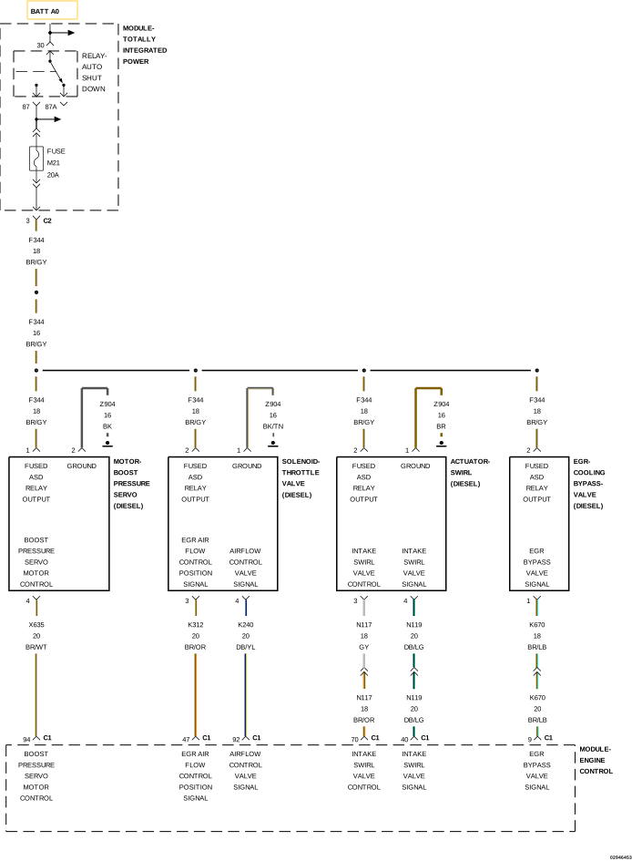 |
For a complete wiring diagram, refer to the Wiring Information.
Theory of Operation
The Intake Swirl Valve is located under the Intake Manifold. The Intake Swirl Valve is supplied 12 Volts by the ASD circuit and has a dedicated ground. It is controlled using a Pulse Width Modulated (PWM) circuit by the Powertrain Control Module (PCM). The Intake Swirl Valve has an internal position sensor that is monitored by the PCM over the (N119) Intake Swirl Valve Signal circuit. The Intake Swirl Valve is used to create turbulence in the air entering the combustion chamber which helps to reduce emissions.
-
When Monitored:
With the ignition on and the intake Swirl Valve commanded off.
-
Set Condition:
The Powertrain Control Module (PCM) detects that the (N117) Intake Swirl Valve Control circuit is shorted to ground for 0.5 second.
Possible Causes |
|---|
| (N117) INTAKE SWIRL VALVE CONTROL CIRCUIT SHORTED TO GROUND |
| INTAKE SWIRL VALVE |
| POWERTRAIN CONTROL MODULE (PCM) |
Always perform the Pre-Diagnostic Troubleshooting procedure before proceeding. (Refer to 28 - DTC-Based Diagnostics/MODULE, Powertrain Control (PCM) - Standard Procedure).
| 1. | Turn the ignition on. |
| 2. | Using the scan tool, erase PCM DTCs. |
| 3. | Using the scan tool, navigate to Actuator Tests and actuate the Variable Swirl Valve. |
| 4. | Using the scan tool, view PCM DTCs. |
Did this DTC return?
Yes
- Go To 2
No
- Perform the INTERMITTENT DTC diagnostic procedure. (Refer to 28 - DTC-Based Diagnostics/MODULE, Powertrain Control (PCM) - Standard Procedure)
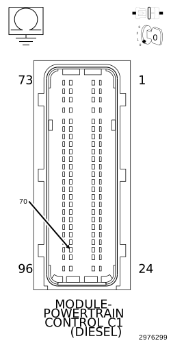
2. CHECK THE (N117) INTAKE SWIRL VALVE CONTROL CIRCUIT FOR A SHORT TO GROUND
 |
| 1. | Turn the ignition off. |
| 2. | Disconnect the Intake Swirl Valve harness connector. |
| 3. | Disconnect the PCM C1 harness connector. |
| 4. | Measure the resistance between ground and the (N117) Intake Swirl Valve Control circuit at the PCM C1 harness connector. |
Is the resistance above 10k Ohms?
Yes
- Go To 3
No
- Repair the (N117) Intake Swirl Valve Control circuit for a short to ground.
-
Perform the PCM VERIFICATION TEST. (Refer to 28 - DTC-Based Diagnostics/MODULE, Powertrain Control (PCM)
- Standard Procedure).
| 1. | Replace the Intake Swirl Valve in accordance with the service information. |
| NOTE: | Make sure the PCM and Intake Swirl Valve harness connectors are connected. |
| 2. | Turn the ignition on. |
| 3. | Using the scan tool, erase PCM DTCs. |
| 4. | Using the scan tool, navigate to Actuator Tests and actuate the Variable Swirl Valve. |
| 5. | Using the scan tool, view PCM DTCs. |
Did this DTC return?
Yes
- Replace and program the Powertrain Control Module in accordance with the service information.
- Perform the PCM VERIFICATION TEST. (Refer to 28 - DTC-Based Diagnostics/MODULE, Powertrain Control (PCM) - Standard Procedure).
No
- Test complete.
- Perform the PCM VERIFICATION TEST. (Refer to 28 - DTC-Based Diagnostics/MODULE, Powertrain Control (PCM) - Standard Procedure).