P2101-ELECTRONIC THROTTLE CONTROL MOTOR PERFORMANCE
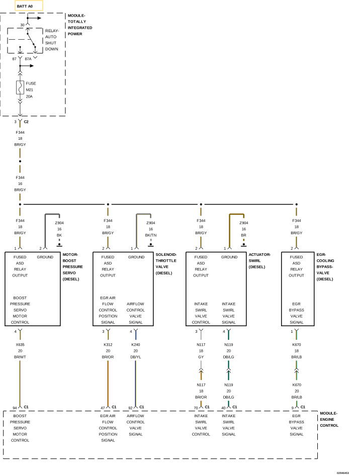
For a complete wiring diagram, refer to the Wiring Information.
Theory of Operation
The Exhaust Gas Recirculation (EGR) Air Flow Control Valve is a two-wire electrically operated throttle valve motor used to assist the EGR system function by creating a vacuum in the intake system to draw exhaust gas into the intake manifold. The Solenoid receives 12 volts from the PCM/ASD relay and a pulse-width modulated ground signal from the PCM. With the solenoid de-energized (off) the throttle valve is in the open (full flow) position. When the PCM energizes (grounds) the throttle motor, the throttle valve closes creating a low pressure (vacuum) in the intake system. This low pressure effect helps draw exhaust gases from the EGR Valve into the intake system. When this DTC is active, the EGR System and DPF regeneration is disabled.
When Monitored:
With the ignition on and the Powertrain Control Module (PCM) Exhaust Gas Recirculation (EGR) Air Flow Control Valve command off.
Set Condition:
The Powertrain Control Module (PCM) detects an implausible signal on the EGR Air Flow Control Valve Control circuit for 0.5 seconds.
Possible Causes
HIGH RESISTANCE IN THE (K312) EGR AIR FLOW CONTROL VALVE CONTROL CIRCUIT
2.
CHECK FOR HIGH RESISTANCE IN THE (K312) EGR AIR FLOW CONTROL VALVE CONTROL CIRCUIT
1.
Turn the ignition off.
2.
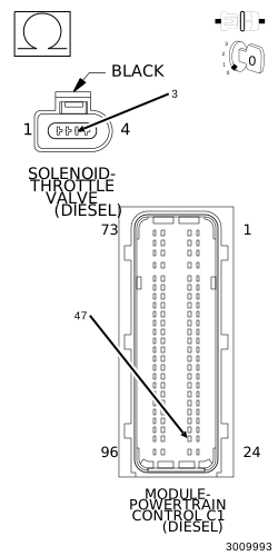
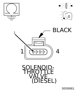
Disconnect the EGR Air Flow Control Valve harness connector.
3.
Disconnect the PCM C1 harness connector.
4.
Measure the resistance of the (K312) EGR Air Flow Control Valve Control circuit between the EGR Air Flow Control Valve harness connector and the PCM C1 harness connector.