P2455-DIESEL PARTICULATE FILTER DIFFERENTIAL PRESSURE SENSOR CIRCUIT HIGH
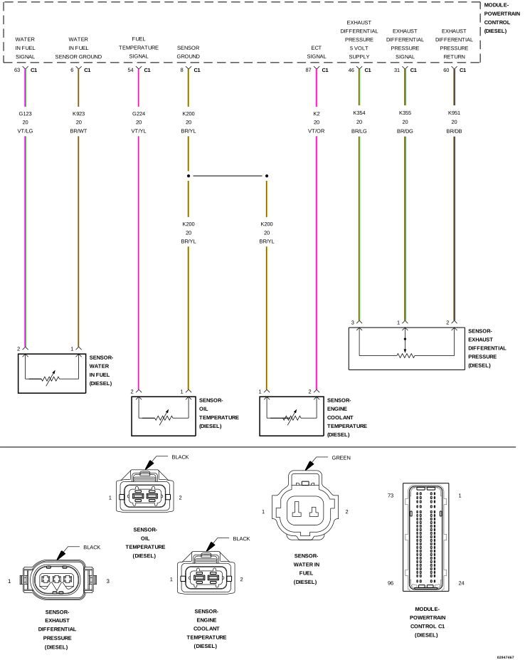 |
For a complete wiring diagram, refer to the Wiring Information.
Theory of Operation
The Diesel Particulate Filter is an in-line canister filter located in the exhaust system between the engine and the muffler. This filter captures and stores soot particles created by the diesel combustion process. As ash and soot accumulate in the filter, the exhaust pressure at the inlet side of the filter increases as compared to the pressure at the outlet side of the filter. This filter is monitored by the Powertrain Control Module (PCM) with a Differential Pressure Sensor. There is a tube at the inlet and outlet of the Diesel Particulate Filter. A hose is attached to each tube. The other end of the hose is connected to the Differential Pressure Sensor. The Differential Pressure Sensor compares the pressure from each hose and measures the delta pressure (difference between the inlet and outlet) in the Diesel Particulate Filter.
-
When Monitored:
With the ignition on.
-
Set Condition:
The (K355) Exhaust Differential Pressure Sensor signal is above 4.59 Volts for 0.5 second.
Possible Causes |
|---|
| (K354) EXHAUST DIFFERENTIAL PRESSURE SENSOR 5-VOLT SUPPLY CIRCUIT SHORTED TO VOLTAGE |
| (K355) EXHAUST DIFFERENTIAL PRESSURE SENSOR SIGNAL CIRCUIT SHORTED TO VOLTAGE |
| (K951) EXHAUST DIFFERENTIAL PRESSURE SENSOR GROUND CIRCUIT OPEN/HIGH RESISTANCE |
| EXHAUST DIFFERENTIAL PRESSURE SENSOR |
| POWERTRAIN CONTROL MODULE (PCM) |
Always perform the Pre-Diagnostic Troubleshooting procedure before proceeding. (Refer to 28 - DTC-Based Diagnostics/MODULE, Powertrain Control (PCM) - Standard Procedure).
| NOTE: | If any Sensor Reference DTCs are present, perform the applicable diagnostic procedure before continuing with this test. |
| 1. | Ignition on, engine not running. |
| 2. | With the scan tool, select View DTCs. |
Is the status Active for this DTC?
Yes
- Go To 2
No
- Perform the INTERMITTENT DTC diagnostic procedure. (Refer to 28 - DTC-Based Diagnostics/MODULE, Powertrain Control (PCM) - Standard Procedure).
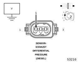
2. CHECK THE (K355) EXHAUST DIFFERENTIAL PRESSURE SENSOR SIGNAL CIRCUIT FOR A SHORT TO VOLTAGE
 |
| 1. | Turn the ignition off. |
| 2. | Disconnect the Exhaust Differential Pressure Sensor harness connector. |
| 3. | Turn the ignition on. |
| 4. | Measure the voltage of the (K355) Exhaust Differential Pressure Sensor Signal circuit in the Exhaust Differential Pressure Sensor harness connector. |
Is the voltage above 5.0 Volts?
Yes
- Repair the (K355) Exhaust Differential Pressure Sensor Signal circuit for a short to voltage.
- Perform the PCM VERIFICATION TEST. (Refer to 28 - DTC-Based Diagnostics/MODULE, Powertrain Control (PCM) - Standard Procedure).
No
-
Go To 3
3. CHECK THE (K951) EXHAUST DIFFERENTIAL PRESSURE SENSOR GROUND CIRCUIT FOR AN OPEN/HIGH RESISTANCE
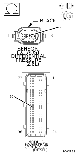 |
| 1. | Disconnect the PCM C1 harness connector. |
| 2. | Measure the resistance of the (K951) Exhaust Differential Pressure Sensor Ground circuit between the Exhaust Differential Pressure Sensor harness connector and the PCM C1 harness connector. |
Is the resistance below 5.0 Ohms?
Yes
- Go To 4
No
- Repair the (K951) Exhaust Differential Pressure Sensor Ground circuit for an open or high resistance.
-
Perform the PCM VERIFICATION TEST. (Refer to 28 - DTC-Based Diagnostics/MODULE, Powertrain Control (PCM)
- Standard Procedure).
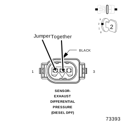
4. EXHAUST DIFFERENTIAL PRESSURE SENSOR
 |
| 1. | Turn the ignition off. |
| 2. | Reconnect the PCM C1 harness connector. |
| 3. | Connect a jumper wire between the (K951) Exhaust Differential Pressure Sensor Ground circuit and the (K355) Exhaust Differential Pressure Sensor Signal circuit in the Exhaust Differential Pressure Sensor harness connector. |
| 4. | Turn the ignition on. |
| 5. | With the scan tool, view DTCs. |
| NOTE: | The scan tool should display a P2454-Exhaust Differential Pressure Sensor Low DTC with the jumper wire in place. |
Does the scan tool display the DTC as described above?
Yes
- Replace the Exhaust Differential Pressure Sensor in accordance with the service information.
- Perform the PCM VERIFICATION TEST. (Refer to 28 - DTC-Based Diagnostics/MODULE, Powertrain Control (PCM) - Standard Procedure).
No
-
Go To 5
| 1. | Using the wiring diagram/schematic as a guide, inspect the wiring and connectors between the Exhaust Differential Pressure Sensor and the Powertrain Control Module (PCM). |
| 2. | Look for any chafed, pierced, pinched, or partially broken wires. |
| 3. | Look for broken, bent, pushed out or corroded terminals. |
| 4. | Perform any Technical Service Bulletins that may apply. |
Were any problems found?
Yes
- Repair as necessary.
- Perform the PCM VERIFICATION TEST. (Refer to 28 - DTC-Based Diagnostics/MODULE, Powertrain Control (PCM) - Standard Procedure).
No
- Replace the Powertrain Control Module in accordance with the service information.
- Perform the PCM VERIFICATION TEST. (Refer to 28 - DTC-Based Diagnostics/MODULE, Powertrain Control (PCM) - Standard Procedure).