P2463-DIESEL PARTICULATE FILTER - SOOT ACCUMULATION
For a complete wiring diagram, refer to the Wiring Information.
Theory of Operation
The Diesel Particulate Filter is an in-line canister filter located in the exhaust system between the engine and the muffler. This filter captures and stores soot particles created by the diesel combustion process. As ash and soot accumulate in the filter, the exhaust pressure at the inlet side of the filter increases as compared to the pressure at the outlet side of the filter. This filter is monitored by the Powertrain Control Module (PCM) with a Differential Pressure Sensor. There is a tube at the inlet and outlet of the Diesel Particulate Filter. A hose is attached to each tube. The other end of the hose is connected to the Differential Pressure Sensor. The Differential Pressure Sensor compares the pressure from each hose and measures the delta pressure (difference between the inlet and outlet) in the Diesel Particulate Filter.
-
When Monitored:
With the engine running.
-
Set Condition:
The Powertrain Control Module (PCM) detects that the Diesel Particulate Filter has reached it's maximum soot load capacity.
Possible Causes |
|---|
| RESTRICTED AIR FILTER |
| INTAKE SYSTEM LEAK OR RESTRICTION |
| EXHAUST SYSTEM LEAK OR RESTRICTION |
| FUEL DELIVERY SYSTEM ISSUES CAUSING EXCESSIVE SOOT ACCUMULATION |
| HIGH RESISTANCE IN EXHAUST DIFFERENTIAL PRESSURE SENSOR CIRCUITS |
| EXHAUST DIFFERENTIAL PRESSURE SENSOR |
| POWERTRAIN CONTROL MODULE (PCM) |
Always perform the Pre-Diagnostic Troubleshooting procedure before proceeding. (Refer to 28 - DTC-Based Diagnostics/MODULE, Powertrain Control (PCM) - Standard Procedure).
| NOTE: | If any Sensor Reference DTCs are present, perform the applicable diagnostic procedure before continuing with this test. |
| 1. | Ignition on, engine not running. |
| 2. | With the scan tool, Clear DTCs in the PCM. |
| 3. | Start the engine. |
| 4. | Allow the engine to reach normal operating temperature. |
| 5. | With the scan tool, select View DTCs. |
Is the status Active for this DTC?
Yes
- Go To 2
No
- Perform the INTERMITTENT CONDITION diagnostic procedure. (Refer to 28 - DTC-Based Diagnostics/MODULE, Powertrain Control (PCM) - Standard Procedure).
| 1. | Turn the ignition off. |
| 2. | Remove and inspect the Air Filter for soiling or excessive dirt and debris which may cause air flow restriction. |
| 3. | Check the Inlet Tube for signs of excessive dirt, snow, or ice restricting airflow into the Air Filter Box. |
Were any problems found?
Yes
- Repair or replace as necessary.
- Perform the PCM VERIFICATION TEST. (Refer to 28 - DTC-Based Diagnostics/MODULE, Powertrain Control (PCM) - Standard Procedure).
No
- Go To 3
3. CHECK FOR INTAKE SYSTEM RESTRICTIONS
| 1. | Turn the ignition off. |
| 2. | Inspect all air intake, crankcase vent and Turbocharger related hoses/tubes and connections. |
| 3. | Inspect the Charge Air Cooler hoses/tubes and connections. |
| 4. | Inspect the EGR Air Flow Control Valve to ensure the valve is not stuck in the closed position. |
Were any problems found?
Yes
- Repair or replace as necessary.
- Perform the PCM VERIFICATION TEST. (Refer to 28 - DTC-Based Diagnostics/MODULE, Powertrain Control (PCM) - Standard Procedure).
No
- Go To 4
4. CHECK FOR INTAKE SYSTEM AIR LEAKS
| 1. | Remove the Crankcase Vent Heater. |
| 2. | Remove the Mass Air Flow Sensor from the Turbocharger Inlet Tube. |
| 3. | Seal off and/or plug the Turbocharger Inlet Tube where the MAF sensor was removed. |
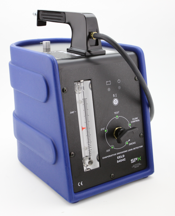
| 4. | Connect the Evaporative Emissions Leak Detector (EELD) Kit, EELD And Accessory 8404C to the Crankcase Vent Heater port in the intake duct and begin injecting smoke into the intake system. |
| 5. | Observe all intake system components for evidence of smoke leakage. |
Is there evidence of smoke leakage?
Yes
- Repair or replace as necessary.
- Perform the PCM VERIFICATION TEST. (Refer to 28 - DTC-Based Diagnostics/MODULE, Powertrain Control (PCM) - Standard Procedure).
No
- Go To 5
5. CHECK THE EXHAUST SYSTEM FOR LEAKS OR RESTRICTIONS
| 1. | Visually inspect the entire exhaust system for damage, leaks or restrictions. |
Were any problems found?
Yes
- Repair as necessary.
- Perform the PCM VERIFICATION TEST. (Refer to 28 - DTC-Based Diagnostics/MODULE, Powertrain Control (PCM) - Standard Procedure).
No
- Go To 6
6. CHECK THE FUEL DELIVERY SYSTEM
| 1. | Perform the CHECKING THE FUEL DELIVERY SYSTEM diagnostic procedure. (Refer to 29 - Non-DTC Diagnostics/Drivability - Diesel - Diagnosis and Testing) . |
Were any problems found?
Yes
- Repair as necessary.
- Perform the PCM VERIFICATION TEST. (Refer to 28 - DTC-Based Diagnostics/MODULE, Powertrain Control (PCM) - Standard Procedure).
No
- Go To 7
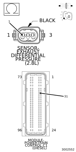
7. CHECK THE (K355) EXHAUST DIFFERENTIAL PRESSURE SENSOR SIGNAL CIRCUIT FOR AN OPEN/HIGH RESISTANCE
 |
| 1. | Turn the ignition off. |
| 2. | Disconnect the Exhaust Differential Pressure Sensor harness connector. |
| 3. | Disconnect the PCM C1 harness connector. |
| 4. | Measure the resistance of the (K355) Exhaust Differential Pressure Sensor Signal circuit between the Exhaust Differential Pressure Sensor harness connector and the Powertrain Control Module (PCM) harness connector. |
Is the resistance below 5.0 Ohms?
Yes
- Go To 8
No
- Repair the (K355) Exhaust Differential Pressure Sensor Signal circuit for an open or high resistance.
-
Perform the PCM VERIFICATION
TEST. (Refer to 28 - DTC-Based
Diagnostics/MODULE, Powertrain Control (PCM)
- Standard Procedure).
8. CHECK THE (K951) EXHAUST DIFFERENTIAL PRESSURE SENSOR GROUND CIRCUIT FOR AN OPEN/HIGH RESISTANCE
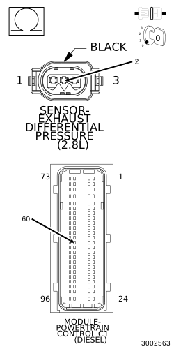 |
| 1. | Measure the resistance of the (K951) Exhaust Differential Pressure Sensor Ground circuit between the Exhaust Differential Pressure Sensor harness connector and the Powertrain Control Module (PCM) harness connector. |
Is the resistance below 5.0 Ohms?
Yes
- Go To 9
No
- Repair the (K951) Exhaust Differential Pressure Sensor Ground circuit for an open or high resistance.
-
Perform the PCM VERIFICATION
TEST. (Refer to 28 - DTC-Based
Diagnostics/MODULE, Powertrain Control (PCM)
- Standard Procedure).
9. EXHAUST DIFFERENTIAL PRESSURE SENSOR
| 1. | Turn the ignition off. |
| 2. | Reconnect the PCM C1 harness connector. |
| 3. | Replace the Exhaust Differential Pressure Sensor in accordance with the service information. |
| 4. | Turn the ignition on. |
| 5. | With the scan tool, clear DTCs. |
| 6. | Start the engine. |
| 7. | Allow the engine to reach normal operating temperature. |
| 8. | With the scan tool, select View DTCs. |
Did the DTC return?
Yes
- Go To 10
No
- Repair complete.
- Perform the PCM VERIFICATION TEST. (Refer to 28 - DTC-Based Diagnostics/MODULE, Powertrain Control (PCM) - Standard Procedure).
10. PARTICULATE FILTER REGENERATION
| 1. | Turn the ignition on. |
| 2. | With the scan tool, erase DTCs in the PCM. |
| 3. | Start and idle the engine. |
| 4. | With the scan tool, perform the Diesel Particulate Filter Regeneration procedure. |
| 5. | After this procedure is complete, turn the ignition off for 60 seconds. |
| 6. | Test drive the vehicle. |
| 7. | With the scan tool, view DTCs in the PCM. |
Is the status Active for this DTC?
Yes
- Go To 11
No
- Test complete.
- Perform the PCM VERIFICATION TEST. (Refer to 28 - DTC-Based Diagnostics/MODULE, Powertrain Control (PCM) - Standard Procedure).
| 1. | Using the wiring diagram/schematic as a guide, inspect the wiring and connectors between the Exhaust Differential Pressure Sensor and the Powertrain Control Module. |
| 2. | Look for any chafed, pierced, pinched, or partially broken wires. |
| 3. | Look for broken, bent, pushed out or corroded terminals. |
| 4. | Perform any Technical Service Bulletins that may apply. |
Were any problems found?
Yes
- Repair as necessary.
- Perform the PCM VERIFICATION TEST. (Refer to 28 - DTC-Based Diagnostics/MODULE, Powertrain Control (PCM) - Standard Procedure).
No
- Replace the Powertrain Control Module in accordance with the service information.
- Perform the PCM VERIFICATION TEST. (Refer to 28 - DTC-Based Diagnostics/MODULE, Powertrain Control (PCM) - Standard Procedure).