PCM/ECM / TCM PROGRAMMING
PCM/ECM / TCM FLASH PROGRAMING
This procedure will need to be done when one or more of the following situations are true:
- A vehicle’s Powertrain Control Module/Engine Control Module (PCM/ECM) has been replaced.
- A diagnostic trouble code (DTC) is set P1602 - PCM/ECM Not Programmed.
- An updated calibration or software release is available for either the PCM/ECM or TCM ECUs.
This procedure assumes that the wiTECH™ Vehicle Connection Interface (VCI) pod, StarSCAN® and StarMOBILE® devices are configured to your dealership’s network with either a wired or wireless connection. The wiTECH™ VCI pod, StarSCAN® and StarMOBILE® must also be running at the latest operating system and software release level. For more help on how to network your StarSCAN® or StarMOBILE® reference the StarSCAN® / StarMOBILE® Quick Start Networking Guide available on ‘DealerCONNECT > Service > StarSCAN® and StarMOBILE® Tools > Online Documentation’ or at www.dcctools.com, under the Download Center. For the wiTECH™ VCI pod use the "HELP" tab in the wiTECH™ Diagnostic Application.
Table of contents
- SECTION 1 – PCM/ECM / TCM FLASH PROCEDURE SECTION 1 - PCM/ECM/TCM FLASH PROCEDURE
- REQUIRED TOOLS/EQUIPMENT REQUIRED TOOLS / EQUIPMENT:
- TECH TIPS and INFORMATION TECH TIPS and INFORMATION:
- PARTS REQUIRED PARTS REQUIRED
SECTION 1 - PCM/ECM/TCM FLASH PROCEDURE
If using StarSCAN® or StarMOBILE® Desktop Client. Refer to REPAIR PROCEDURE – Using StarSCAN® or StarMOBILE® Desktop Client.
If using wiTECH™ Diagnostic Application. Refer to REPAIR PROCEDURE – wiTECH™ Diagnostic Application.
REPAIR PROCEDURE – Using StarSCAN® or StarMOBILE® Desktop Client
| NOTE: |
If this flash process is interrupted or aborted, the flash should be restarted. |
- Open the hood of the vehicle and install a battery charger. Verify that the charging rate provides a continuous charge of 13.2 – 13.5 Volts.
- Connect the StarSCAN® or StarMOBILE® to the vehicle data link connector located under the steering column and turn the ignition key to the “RUN” position.
- Power on the StarSCAN® or StarMOBILE®. If the StarMOBILE® is being used, launch the StarMOBILE® Desktop Client and connect to the appropriate StarMOBILE® device.
-
Retrieve the old ECU
part number. From the tool’s Home screen,
- Select “ECU View”
- Select “PCM/ECM”
- Select “More Options”
- Select “ECU Flash”
- Record the part number at the top of the Flash PCM/ECM screen for later reference.
- Program the ECU as follows:
- Using the StarSCAN® / StarMOBILE® at the Home screen, select “ECU View”
- Select “PCM/ECM”
- Select “More Options”
- Select “ECU Flash”
- Select “Browse for New File” and follow the on screen instructions
- Highlight the appropriate calibration based on the part number recorded in Step 4e, or by using Year/Model/Engine and appropriate emissions selection for the vehicle being worked on
- Select “Download to Client/Scantool”
- Once the download is complete, select “Close” and then “Back”
- Highlight the listed calibration, select “Update Controller” and follow the on screen instructions
- When the PCM/ECM update is complete, select “OK”
- Verify that the part number at the top of the Flash PCM/ECM screen has updated to the new part number
NOTE: If this flash process is interrupted or aborted, the flash should be restarted.
- Continue to complete the process if the ECU has been replaced.
- Type the necessary information on the “Authorized Modification Label” (p/n 04275086AB) and attach near the VECI label (See SECTION 3 – AUTHORIZED MODIFCATION LABEL for details).
REPAIR PROCEDURE – wiTECH™ Diagnostic Application
| NOTE: |
If this flash process is interrupted or aborted, the flash should be restarted. |
- Open the hood of the vehicle and install a battery charger. Verify that the charging rate provides a continuous charge of 13.2 – 13.5 Volts.
- Connect the wiTECH™ Vehicle Connection Interface (VCI) pod to the vehicle data link connector located under the steering column and turn the ignition key to the “RUN” position.
- Launch the wiTECH™ Diagnostic Application and connect to the appropriate wiTECH™ device.
- From the wiTECH™ Diagnostic Application Home screen,
SECTION 2 – ADDITIONAL PCM/ECM / TCM REPLACEMENT PROCEDURES
| NOTE: |
Find the PCM/ECM /TCM Type for the vehicle, read and write down the steps, and then go to the step by step instructions for additional information on how to perform these procedures. STEP-BY-STEP INSTRUCTIONS |
If a 2.0L Controller was replaced, navigate to “Misc. Functions” and perform all applicable routines:
| NOTE: |
The available routines may vary depending on model and year of vehicle. |
- PCM/ECM Replaced – Located within the Security Module
-
ECU Replacement With
Value Transfer - if the ECU to be replaced is still responsive
NOTE: If the PCM/ECM data transfer is able to be completed, it may not be necessary to perform routines 7 - 9.
- ECU Replacement Without Value Transfer - if the ECU to be replaced is NOT responsive
- Verify PCM/ECM VIN
- Injector Quantity Adjustment (For 2012 and older applications only)
- Program Variant Code
- Service Diesel Particulate Filter Regeneration
- Reset Zero Fuel
- Reset of Lambda Values
If a PT Cruiser, 2.2L Controller was replaced, navigate to “Misc. Functions” and perform all applicable routines:
| NOTE: |
The available routines may vary depending on model and year of vehicle. |
- PCM/ECM Replaced – Located within the Security Module
- Injector Quantity Adjustment – Only on 06 PT AND up
- IMA Rapid Calibration Test - Only on 06 PT AND up
If a 3.0L Controller was replaced, navigate to “Misc. Functions” and perform all applicable routines:
| NOTE: |
The available routines may vary depending on model and year of vehicle. |
- PCM/ECM Replaced – Located within the Security Module
-
ECU Replacement With Value Transfer - if the ECU to be replaced is still responsive
NOTE: If the PCM/ECM data transfer is able to be completed, it may not be necessary to perform routines 7 - 12.
- ECU Replacement Without Value Transfer - if the ECU to be replaced is NOT responsive
- Injector Quantity Adjustment
- Program Variant Code
- Verify PCM/ECM VIN
- Diesel Particulate Filter (Used) Learning
- Reset of Lambda Values
- Reset Zero Fuel
- NOx Catalyst (New) Initialization
- IMA Rapid Calibration Test
- Fuel Mean Value Adaptation Initialization
- Exhaust Throttle Plate Adaptive Learn Position
If a 2.8L Controller was replaced, navigate to “Misc. Functions” and perform all applicable routines:
| NOTE: |
The available routines may vary depending on model and year of vehicle. |
- PCM/ECM Replaced – Located within the Security Module
-
ECU Replacement With Value Transfer - if the ECU to be replaced is still responsive
NOTE: If the PCM/ECM data transfer is able to be completed, it may not be necessary to perform routines 6 - 8.
- ECU Replacement Without Value Transfer - if the ECU to be replaced is NOT responsive
- Injector Quantity Adjustment
- Program Variant Code
- Fuel Mean Value Adaptation Initialization
- IMA Rapid Calibration Test
- Set Oil Dilution Mass Value
If a PM/MK, 2.2L Controller was replaced, navigate to “Misc. Functions” and perform all applicable routines:
| NOTE: |
The available routines may vary depending on model and year of vehicle. |
- PCM/ECM Replaced – Located within the Security Module
-
Engine ECU Replacement
NOTE: If the PCM/ECM data transfer is able to be completed, it may not be necessary to perform routines 5 - 10.
- Injector Quantity Adjustment
- Program Variant Code
- Swirl Control Learn
- Throttle Valve Learn
- VGT Learn
- MAF Sensor Replace
- O2 Sensor Replace
- Used DPF initialize
If a 5.9L Controller was replaced, navigate to “Misc. Functions” and perform all applicable routines:
| NOTE: |
The available routines may vary depending on model and year of vehicle. |
If a 6.7L Controller was replaced, navigate to “Misc. Functions” and perform all applicable routines:
| NOTE: |
The available routines may vary depending on model and year of vehicle. |
- PCM/ECM Replaced – Located within the Security Module
- Injector Quantity Adjustment
- Enable / Disable Vehicle Features – need to enable features
- Set max vehicle speed
- Set max cruise speed
- Idle shutdown timer
- PTO RPM adjustment
-
Set PTO Max vehicle speed
NOTE: The numbers can be retrieved from the old PCM/ECM using the scan tool if the PCM/ECM is still functional or they may be retrieved from the Fuel Injectors themselves. The numbers are stamped on the intake manifold side of the injectors.
- Reset Regenerative Filter Timers
If an Aisin TCM was replaced, perform the following additional steps and/or routines:
If an EATX TCM was replaced, perform the following additional steps and/or routines:
If an NGC3 TCM ONLY was replaced, perform the following additional steps and/or routines:
If an NGC4 TCM ONLY was replaced, perform the following additional steps and/or routines:
If an EGS TCM was replaced, perform the following additional steps and/or routines:
STEP-BY-STEP INSTRUCTIONS
PCM/ECM Replaced
The vehicle pin (Personal Identification Number) will be required to complete the routine. This information may be obtained in three ways:
From the “Home” screen, select “ECU View”
- Select the applicable Security Module
- Select “Misc. Functions”
- Select “PCM/ECM Replaced” and follow the on screen instructions.
- When complete, select “Finish”
Check PCM VIN
From the “Home” screen, select “ECU View”
- Select “PCM/ECM”
- Select “Misc. Functions”
- Select “Check PCM/ECM VIN” and follow the on screen instructions.
- When complete, select “Finish”
Diesel Particulate Filter (Used) Learning
From the “Home” screen, select “ECU View”
- Select “PCM/ECM”
- Select “Misc. Functions”
- Select “Diesel Particulate Filter (Used) Learning” and follow the on screen instructions.
- When complete, select “Finish”
ECU Replacement with Value Transfer
From the “Home” screen, select “ECU View”
- Select “PCM/ECM”
- Select “Misc. Functions”
- Select “ECU Replacement with Value Transfer” and follow the on screen instructions.
- When complete, select “Finish”
ECU Replacement without Value Transfer
From the “Home” screen, select “ECU View”
- Select “PCM/ECM”
- Select “Misc. Functions”
- Select “ECU Replacement without Value Transfer” and follow the on screen instructions.
- When complete, select “Finish”
Enable / Disable Vehicle Features
From the “Home” screen, select “ECU View”
- Select “PCM/ECM”
- Select “Misc. Functions”
- Select “Enable / Disable Vehicle Features” and follow the on screen instructions.
- When complete, select “Finish”
Exhaust Throttle Plate Adaptive Learn Position
From the “Home” screen, select “ECU View”
- Select “PCM/ECM”
- Select “Misc. Functions”
- Select “Exhaust Throttle Plate Adaptive Learn Position” and follow the on screen instructions.
- When complete, select “Finish”
Fuel Mean Value Adaptation Initialization
From the “Home” screen, select “ECU View”
- Select “PCM/ECM”
- Select “Misc. Functions”
- Select “Fuel Mean Value Adaptation Initialization” and follow the on screen instructions.
- When complete, select “Finish”
IMA Rapid Calibration
From the “Home” screen, select “ECU View”
- Select “PCM/ECM”
- Select “Misc. Functions”
- Select “IMA Rapid Calibration Test” and follow the on screen instructions.
- When complete, select “Finish”
Initialize EGS
From the “Home” screen, select “ECU View”
- Select “PCM/ECM”
- Select “Misc. Functions”
- Select “Initialize EGS” and follow the on screen instructions.
- When complete, select “Finish”
Injector Quantity Adjustment
From the “Home” screen, select “ECU View”
- Select “PCM/ECM”
- Select “Misc. Functions”
- Select “Injector Quantity Adjustment” and follow the on screen instructions.
- When complete, select “Finish”
Mobile DeSoot - NO Minimum Required Soot Load
From the “Home” screen, select “ECU View”
- Select “PCM/ECM”
- Select “Misc. Functions”
- Select “Mobile DeSoot – NO Minimum Required Soot Load” and follow the on screen instructions.
- When complete, select “Finish”
NOx Catalyst (New) Initialization
From the “Home” screen, select “ECU View”
- Select “PCM/ECM”
- Select “Misc. Functions”
- Select “NOx Catalyst (New) Initialization” and follow the on screen instructions.
- When complete, select “Finish”
Program Variant Code
From the “Home” screen, select “ECU View”
- Select “PCM/ECM”
- Select “Misc. Functions”
- Select “Program Variant Code” and follow the on screen instructions.
- When complete, select “Finish”
Quicklearn
From the “Home” screen, select “ECU View”
- Select “PCM/ECM”
- Select “Misc. Functions”
- Select “Quicklearn” and follow the on screen instructions.
- When complete, select “Finish”
Reset Regenerative Filter Timers
From the “Home” screen, select “ECU View”
- Select “PCM/ECM”
- Select “Misc. Functions”
- Select “Reset Regenerative Filter Times” and follow the on screen instructions.
- When complete, select “Finish”
Set Oil Dilution Mass Value
From the “Home” screen, select “ECU View”
- Select “PCM/ECM”
- Select “Misc. Functions”
- Select “Set Oil Dilution Mass Value” and follow the on screen instructions.
- When complete, select “Finish”
SECTION 3 – AUTHORIZED MODIFCATION LABEL
| NOTE: |
The following step is required by law when reprogramming a PCM/ECM and/or TCM. |
Type the necessary information on the “Authorized Modification Label” and attach near the VECI label.
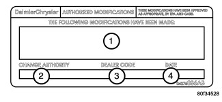 |
- Powertrain Control / Transmission Control Module Part Numbers (Insert P/Ns) Used
- Change Authority: TSB XX--XX
- Dealer Code: XXXXX
-
Date: XX-XX-XX
REQUIRED TOOLS / EQUIPMENT:
| StarSCAN® | StarMOBILE® | wiTECH™ |
|---|---|---|
|
Battery Charger |
Battery Charger |
Battery Charger |
|
StarSCAN® Tool Kit |
StarMOBILE® Tool Kit |
wiTECH™ Tool Kit |
|
StarSCAN® Vehicle Cable |
StarMOBILE® Vehicle Cable |
wiTECH™ Vehicle Cable |
|
TechCONNECT PC or equivalent |
TechCONNECT PC or equivalent |
|
|
wiTECH™ Diagnostic Application |
TECH TIPS and INFORMATION:
Extreme care must be taken when
programming a calibration into a generic PCM. Do not randomly select
a calibration. Once a calibration is selected and programmed, the
controller cannot be reprogrammed to a different calibration. The
module can only be reprogrammed to a more recent version of that calibration.
CAUTION:
- The wiTECH™ Diagnostic Application is the preferred method for flashing any Chrysler vehicle ECU. For more information, training tutorials are available under the "HELP" tab in the wiTECH™ Diagnostic Application or at www.dcctools.com, under the ‘Training Aids’ link.
- To use the StarMOBILE® in Pass-Through Mode requires that your StarMOBILE® is connected to the dealerships network via a wired or wireless connection. For more information on how to use the StarMOBILE in Pass-Through Mode see the StarMOBILE® training tutorials available on ‘DealerCONNECT > Service > StarSCAN® and StarMOBILE® Tools > Training Aids’ link or at www.dcctools.com, under the ‘Training Aids’ link.
- If the flash process is interrupted or aborted, the flash should be restarted.
- Due to the PCM/ECM / TCM programming procedure, a DTC may be set in other ECUs within the vehicle. Some DTCs may cause the MIL to illuminate. From the “Home” screen select “System View”. Then select “All DTCs”. Press “Clear All Stored DTCs” if there are any DTCs shown on the list.
- Do not allow the battery charger to time out or the charging rate to climb above 13.5 Volts during the flash process.
- The StarSCAN® and StarMOBILE® diagnostic tools fully support Internet connectivity and must be configured for your dealership’s network. For help on setting up your StarSCAN® / StarMOBILE® for the dealership’s network, refer to the StarSCAN® / StarMOBILE® Quick Start Networking Guide available on ‘DealerCONNECT > Service > StarSCAN® and StarMOBILE® Tools > Online Documentation’ or at www.dcctools.com, under the download center.
- The operating software in the StarSCAN® and StarMOBILE® must be programmed with the latest software release level. The software level is visible in the blue header at the top of the StarSCAN® and StarMOBILE® Desktop Client screens. For instructions on how to update your scan tool, refer to the StarSCAN® / StarMOBILE® Software Update guide available on ‘DealerCONNECT > Service > StarSCAN® and StarMOBILE® Tools > Online Documentation’ or at www.dcctools.com, under the download center.
PARTS REQUIRED
| Qty | Part Number | DESCRIPTION |
|---|---|---|
|
1 |
04275086AB |
Label, Authorized Modification |