2014 Jeep Wrangler JK Factory Service Manual 28 - DTC-Based Diagnostics

P0563-BATTERY/SYSTEM VOLTAGE HIGH


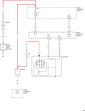
For a complete wiring diagram, refer to the Wiring Information.


Possible Causes

(K20) GENERATOR FIELD CONTROL CIRCUIT SHORTED TO VOLTAGE
GENERATOR
POWERTRAIN CONTROL MODULE (PCM)

Always perform the Pre-Diagnostic Troubleshooting procedure before proceeding. (Refer to 28 - DTC-Based Diagnostics/MODULE, Powertrain Control (PCM) - Standard Procedure).


1. ACTIVE DIAGNOSTIC TROUBLE CODE (DTC)


NOTE: Make sure the Battery is in good condition. Using the Midtronics Battery Tester, test the Battery before continuing.

NOTE: Inspect the vehicle for after market accessories that may exceed the Generator System output.

NOTE: Make sure the Generator drive belt is in good operating condition.

NOTE: Inspect the fuses in the TIPM. If a fuse is open use the wire diagram/schematic as a guide, inspect the wiring and connectors for damage.
1. Ignition on, engine not running.
2. With a scan tool, read the active DTCs.


Is the DTC Active at this time?

Yes


No


2. GENERATOR OPERATION


1. Turn the ignition off.
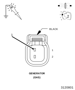
2. Disconnect the Generator Field harness connector.
3. Using a 12-Volt test light connected to ground, probe the (K20) Generator Field Control circuit in the Generator Field harness connector.


NOTE: Make sure the test light is probing the circuit before actuating the Relay or a DTC may set and not allow the actuation.
4. Ignition on, engine not running.
5. Using the scan tool, actuate the Generator Field Control circuit.


Does the test light illuminate brightly and flash on and off?

Yes


No


3. (K20) FIELD CIRCUIT SHORTED VOLTAGE


1. Turn the ignition off.
2. Disconnect the PCM C2 harness connector.
3. Ignition on, engine not running.
4. Measure the voltage on the (K20) Generator Field Control circuit at the Generator Field harness connector.


Is there any voltage present?

Yes


No


4. POWERTRAIN CONTROL MODULE (PCM)


1. Using the wiring diagram/schematic as a guide, inspect the wiring and connectors between the Generator and the Powertrain Control Module (PCM).
2. Look for any chafed, pierced, pinched, or partially broken wires.
3. Look for broken, bent, pushed out or corroded terminals. Verify that there is good pin to terminal contact in the Generator and Powertrain Control Module connectors.
4. Perform any Technical Service Bulletins that may apply.

Were there any problems found?

Yes


No