For a complete wiring diagram, refer to the Wiring
Information.
When Monitored:
Engine running in closed loop mode.
Set Condition:
Enable conditions are met and the O2 sensor has not been in closed loop control at least once on each of the two consecutive trips, the MIL illuminates and the DTC is set. Two Trip Fault. Three good trips to turn off the MIL
Check for contaminants that may have damaged an O2 Sensor: contaminated fuel, unapproved silicone, oil and coolant.
2.
Start the engine.
3.
Allow the engine to reach normal operating temperature.
4.
With the scan tool, read DTCs.
NOTE:
It may be necessary to drive the vehicle to meet the conditions to set this DTC, try to repeat the conditions in which the fault originally set by reviewing the Freeze Frame data.
The fuel system is under a constant
pressure (even with the engine off). Before testing or servicing any
fuel system hose, fitting or line, the fuel system pressure must be
released. Failure to follow these instructions can result in possible
serious or fatal injury.
1.
Turn the ignition off.
2.
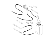
Install Fuel Pressure Decay Tester
8978A
to the fuel rail.
3.
Ignition on, engine not running.
4.
Using the scan tool, actuate the ASD Fuel System test and observe the fuel pressure gauge.
Allow the engine to reach normal operating temperature.
NOTE:
If one of the O2 Sensor's Signal or Return circuit is shorted to ground the scan tool will display all O2 Sensor voltage readings low. The O2 Sensor that is shorted to ground will display a voltage reading near or at 0 Volts.
NOTE:
If one of the O2 Sensor Signal or Return circuits are shorted to voltage, the scan tool will display all O2 Sensor voltage readings high.
NOTE:
After the repairs have been made, verify proper O2 Sensor operation. If all the O2 Sensor voltage readings have not returned to normal, follow the diagnostic procedure for the remaining O2 Sensors.
3.
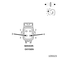
Using the scan tool, monitor the 2/1 O2 Sensor voltage reading.
Is the voltage switching between 2.5 and 3.4 Volts?
For this test to be valid, the thermostat must be operating correctly.
NOTE:
This test works best if performed on a cold engine (cold soak).
1.
Ignition on, engine not running.
2.
Using the scan tool, read the Engine Coolant Temperature (ECT) Sensor value. If the engine was allowed to sit overnight (cold soak), the temperature value should be a sensible value that is somewhere close to the ambient temperature.
NOTE:
If engine coolant temperature is above 82° C (180° F), allow the engine to cool until 65° C (150° F) is reached.
3.
Start the Engine.
4.
During engine warm-up, monitor the ECT Sensor value. The temperature value change should be a smooth transition from start up to normal operating temperature 82° C (180° F). The value should reach at least 82° C (180° F).
Did the ECT value increase smoothly and did it reach at least 82° C (180° F)?
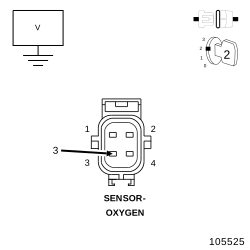
Using the scan tool, monitor all the O2 Sensor voltage reading with the jumper wire removed.
NOTE:
The scan tool will display all O2 Sensor voltage readings approximately 5.0 Volts when only one O2 Sensor's Signal circuit is shorted to voltage.
NOTE:
The scan tool will display one O2 Sensor voltage close to zero and the others will read lower than normal when one O2 Sensor Signal circuit contains excessive resistance.
Using the wiring diagram/schematic as a guide, inspect the wiring and connectors between the related Sensor and the Powertrain Control Module (PCM).
2.
Look for any chafed, pierced, pinched or partially broken wires.
3.
Look for broken, bent, pushed out or corroded terminals. Verify that there is good pin to terminal contact in the related Sensor and Powertrain Control Module connectors.
4.
Perform any Technical Service Bulletins that may apply.
The fuel system is under a constant
pressure (even with the engine off). Before testing or servicing any
fuel system hose, fitting or line, the fuel system pressure must be
released. Failure to follow these instructions can result in possible
serious or fatal injury.
1.
Turn the ignition off.
2.
Raise vehicle on hoist and disconnect the fuel pressure line at the fuel pump module.
3.
Install Fuel Pressure Decay Tester
8978A
between the fuel supply line and the fuel pump module.
4.
Ignition on, engine not running.
5.
Using the scan tool, actuate the ASD Fuel System test and observe the fuel pressure gauge.
The fuel system is under a constant
pressure (even with the engine off). Before testing or servicing any
fuel system hose, fitting or line, the fuel system pressure must be
released.
1.
Turn the ignition off.
2.
Remove the Fuel Pump Module and inspect the Fuel Inlet Strainer.