P2246-O2 SENSOR 1/1, 2/1 REFERENCE VOLTAGE CIRCUIT HIGH
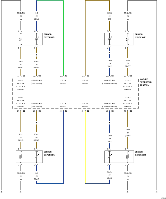
For a complete wiring diagram, refer to the Wiring Information.
Theory of operation
The Oxygen sensors (O2 Sensor) are used for fuel control and catalyst monitoring. Each O2 Sensor compares the oxygen content of the surrounding air with the oxygen content of the exhaust stream. When the engine is started, the Powertrain Control Module (PCM) operates in an Open Loop mode, ignoring the O2 Sensor signal voltage while calculating the air-to-fuel ratio. The heating elements inside each O2 Sensor heatS the sensor to bring the sensor up to operating conditions faster. This allows the system to enter Closed Loop earlier and the PCM to calculate the air-to-fuel ratio sooner. While the engine runs, the O2 Sensor heats up and begins to generate a voltage within a range of 0-1,275 mV. Once sufficient O2 Sensor voltage fluctuation is observed by the PCM, Closed Loop is entered. The PCM uses the O2 Sensor voltage to determine the air-to-fuel ratio. An O2 Sensor voltage that increases toward 1,000 mV indicates a rich fuel mixture. An O2 Sensor voltage that decreases toward 0 mV indicates a lean fuel mixture.
When Monitored:
Engine running for 15 seconds, O2 Sensors at operating temperature and battery voltage greater 10.4 Volts.
Set Condition:
The PCM detects that the (K902) Reference Signal voltage is greater than 3.9 Volts for nine seconds.
Possible Causes
(K902) O2 SENSOR RETURNCIRCUIT SHORTED TO VOLTAGE
(K902) O2 SENSOR RETURNCIRCUIT OPEN OR HIGH RESISTANCE
With the scan tool, select View DTCs. Copy DTC and Freeze Frame information.
3.
Start the engine.
WARNING:
When the engine is operating, do
not stand in direct line with the fan. Do not put your hands near
the pulleys, belts or fan. Do not wear loose clothing. Failure to
follow these instructions may result in possible serious or fatal
injury.
4.
Allow the engine to reach normal operating temperature.
3.
(K902) O2 SENSOR SIGNAL CIRCUIT OPEN OR HIGH RESISTANCE
1.
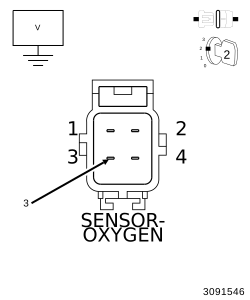
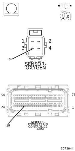
Measure the resistance of the (K902) O2 Sensor Return circuit reference voltage circuit between the O2 Sensor 1/1 or 2/1 harness connector and the PCM C2 harness connector.
With the scan tool, monitor the O2 Sensor 1/1 and 2/1 voltage.
5.
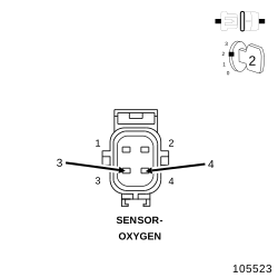
Connect a jumper wire between the (K41) O2 Sensor 1/1 Signal circuit and the (K902) O2 Sensor Return circuit at the O2 Sensor 1/1 harness connector.
6.
Repeat step 5 for the (K43) O2 Sensor 2/1 Signal circuit.
Is the voltage between 2.3 and 2.7 Volts with the jumper wire installed?
Yes
Verify that there is good pin to terminal contact in the O2 Sensors and Powertrain Control Module connectors. Replace the O2 Sensor not indicating the specified voltage if no problems were found with the connections. (Refer to 14 - Fuel System/Fuel Injection/SENSOR, Oxygen - Removal)
.