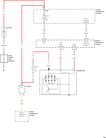
For a complete wiring diagram, refer to the Wiring Information.
When Monitored:
The engine
running. The engine RPM is high enough to assure sufficient Generator
current output to satisfy the electrical loads.
Set Condition:
The battery
sensed voltage is less than the target charging voltage, during engine
operation, for a calibrateable amount of time. One Trip Fault. Generator
light will illuminate.
Possible Causes
LOOSE ACCESSORY
DRIVE BELT
EXCESSIVE RESISTANCE
IN THE BATTERY POSITIVE CIRCUIT
When the engine is operating, do
not stand in direct line with the fan. Do not put your hands near
the pulleys, belts or fan. Do not wear loose clothing. Failure to
follow these instructions may result in possible serious or fatal
injury.
1.
Ignition on, engine not running.
2.
Measure the voltage between the Generator B+ Output Terminal and the Battery + Post.
3.
Start the engine.
Is the voltage above 0.4 Volt?
Yes
Repair the excessive resistance in the battery positive circuit between the Generator and Battery.
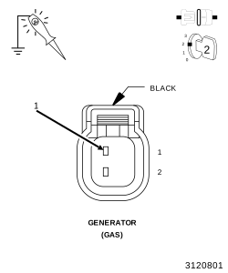
Using a 12-Volt test light connected to ground, probe (K20) Generator Field Control circuit in the Generator Field harness connector.
NOTE:
The DTC needs to be cleared before actuating the Solenoid, if the DTC is not cleared, the Solenoid may not be allowed to actuate.
4.
Ignition on, engine not running.
5.
With a scan tool, actuate the Generator Field Driver.
NOTE:
The test light should be illuminated and bright proportional to the maximum duty cycle allowed by the scan tool. For example, if the scan tool allows 100% actuation, the brightness should be as bright as a direct connection to the battery. If the scan tool allows a maximum 25% actuation, the brightness should be 25% as bright as a direct connection to the battery.
Using the wiring diagram/schematic as a guide, inspect the wiring and connectors between the Generator and the Powertrain Control Module (PCM).
2.
Look for any chafed, pierced, pinched, or partially broken wires.
3.
Look for broken, bent, pushed out or corroded terminals. Verify that there is good pin to terminal contact in the Generator and the Powertrain Control Module connectors.
4.
Perform any Technical Service Bulletins that may apply.