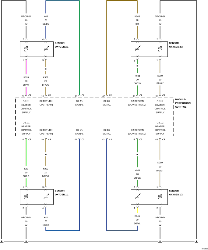
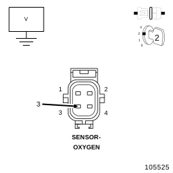
For a complete wiring diagram, refer to the Wiring Information.
Theory of Operation
The fuel feedback system will maintain a stoiciometric fuel/air mixture, 14.7:1, by modifying the injector pulse width according to the oxygen content of the exhaust gas. The Powertrain Control Module (PCM) makes short term and long term fuel corrections to maintain stoiciometric fuel/air ratio for best Catalytic Converter efficiency. Short term fuel correction is based on upstream O2 Sensor output and is designed for quick engine response. The long term fuel correction compensated for variations in the engine specifications, sensor tolerances and component aging and is designed to correct rich and lean conditions over a longer period of time.
When Monitored:
With the engine running in closed loop mode, the ambient/battery temperature above -6.7°C (20°F) and altitude below 2590.8 m (8500 ft).
Set Condition:
If the Powertrain Control Module (PCM) multiplies short term compensation by long term adaptive and a purge fuel multiplier and the result is below a certain value for 30 seconds over two trips, a freeze frame is stored, the MIL illuminates and a trouble code is stored. Two Trip Fault. Three good trips to turn off the MIL.
Possible Causes
EVAP PURGE SOLENOID OPERATION
BANK 1 VVT SOLENOID DRIVER CIRCUIT SHORTED TO VOLTAGE
Check for contaminates that may have damaged an O2 Sensor: contaminated fuel, unapproved silicone, oil and coolant.
1.
Start the engine.
2.
Allow the engine to reach normal operating temperature.
NOTE:
It may be necessary to drive the vehicle to meet the conditions to set this DTC, try to repeat the conditions in which the fault originally set by reviewing the Freeze Frame data.
The fuel system is under a constant
pressure (even with the engine off). Before testing or servicing any
fuel system hose, fitting or line, the fuel system pressure must be
released. Failure to follow these instructions can result in possible
serious or fatal injury.
Allow the engine to reach normal operating temperature.
NOTE:
If one of the O2 Sensors Signal or Return circuit is shorted to ground or voltage, all the other O2 Sensor voltage readings will be affected.
NOTE:
After the repairs have been made, verify proper O2 Sensor operation. If all the O2 Sensor voltage readings have not returned to normal, follow the diagnostic procedure for the remaining O2 Sensors.
3.
Using the scan tool, monitor the O2 Sensor 1/1 voltage reading.
Is the voltage switching between 2.5 and 3.4 Volts?
The Barometric Pressure should be approximately equal to the actual barometric pressure. If necessary, compare the Barometric Pressure value of this vehicle to the value of a known good vehicle of a similar make and model.
3.
Turn the ignition off.
4.
Connect a Vacuum Gauge to a Manifold Vacuum source.
5.
Start the engine.
6.
Allow the engine to idle.
NOTE:
If engine will not idle, maintain a constant RPM above idle.
7.
With the scan tool, read the MAP Sensor vacuum value.
Is the scan tool reading for MAP Vacuum within 1 inch of the Vacuum Gauge reading and is the Barometric Pressure reading of the vehicle the approximately the same as actual Barometric Pressure?
For this test to be valid, the thermostat must be operating correctly.
NOTE:
This test works best if performed on a cold engine (cold soak)
1.
Ignition on, engine not running.
2.
With the scan tool, read the Engine Coolant Temperature Sensor value. If the engine was allowed to sit overnight (cold soak), the temperature value should be a sensible value that is somewhere close to the ambient temperature.
NOTE:
If engine coolant temperature is above 82°C (180°F), allow the engine to cool until 65°C (150°F) is reached.
3.
Start the Engine.
4.
During engine warm-up, monitor the Engine Coolant Temperature value. The temp value change should be a smooth transition from start up to normal operating temp 82°C (180°F). The value should reach at least 82°C (180°F).
Did the ECT value increase smoothly and reach at least 82°C (180°F)?
Perform the following test on the O2 Sensors whose voltage was not switching properly in the previous step.
1.
Ignition on, engine not running.
2.
Disconnect the O2 Sensor 1/1 harness connector.
3.
With the scan tool, monitor the O2 Sensor 1/1 voltage.
4.
O2 Sensor voltage should read between 4.1 and 5.0 Volts on the scan tool with the connector disconnected.
5.
Connect a jumper wire between the (K41) O2 Sensor 1/1 Signal circuit and the (K902) O2 Sensor 1/1 Return circuit in the O2 Sensor 1/1 harness connector.
NOTE:
The voltage should drop from between 4.1 and 5.0 Volts down to 2.5 Volts with the jumper wire connected.
Did the O2 Sensor voltage drop from between 4.1 and 5.0 Volts to 2.5 Volts when the jumper wire was installed?