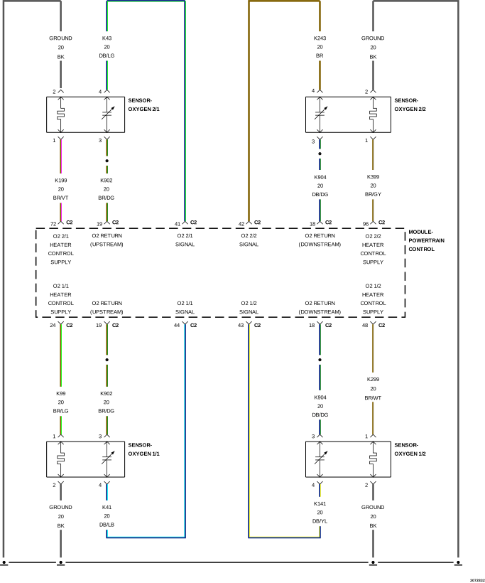
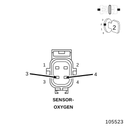
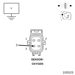
For a complete wiring diagram, refer to the Wiring Information.
Theory of Operation
The fuel feedback system will maintain a stoichiometric fuel/air mixture, 14.7:1, by modifying the injector pulse width according to the oxygen content of the exhaust gas. The Powertrain Control Module (PCM) makes short term and long term fuel corrections to maintain stoichiometric fuel/air ratio for best Catalytic Converter efficiency. Short term fuel correction is based on upstream O2 Sensor output and is designed for quick engine response. The long term fuel correction compensated for variations in the engine specifications, sensor tolerances and component aging and is designed to correct rich and lean conditions over a longer period of time.
When Monitored:
With the engine running in closed loop mode, the ambient/battery temperature above -6.7°C (20°F) and altitude below 2590.8 m (8500 ft).
Set Condition:
If the Powertrain Control Module (PCM) multiplies short term compensation by long term adaptive and a certain percentage is exceeded for two trips, a freeze frame is stored, the MIL illuminates and a trouble code is stored. Two Trip Fault. Three good trips to turn off the MIL.
Check for contaminants that may have damaged an O2 Sensor: contaminated fuel, unapproved silicone, oil and coolant.
1.
Diagnose all other DTCs before continuing.
2.
Start the engine.
3.
Allow the engine to reach normal operating temperature.
4.
With the scan tool, read DTCs.
NOTE:
It may be necessary to drive the vehicle to meet the conditions to set this DTC, try to repeat the conditions in which the fault originally set by reviewing the Freeze Frame data.
The fuel system is under a constant
pressure (even with the engine off). Before testing or servicing any
fuel system hose, fitting or line, the fuel system pressure must be
released. Failure to follow these instructions can result in possible
serious or fatal injury.
Raise the vehicle in accordance with the Service Information.
WARNING:
The normal operating temperature
of the exhaust system is very high. Never work around or attempt to
service any part of the exhaust system until it has cooled. Special
care should be taken when working near the catalytic converter. The
temperature of the converter rises to a high level after a short period
of engine operating time.
3.
Connect the
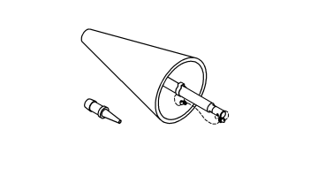
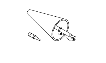
Exhaust Cone 8404-EC
with Air Pressure Regulator (with hose) W-18-MIL-1146AS.
CAUTION:
The air pressure must not exceed
27.6 kPa (4 psi), otherwise engine damage can occur.
4.
Attach shop air to the air pressure regulator.
5.
Adjust the Air Pressure Regulator to 27.6 kPa (4.0 psi).
6.
Insert the exhaust cone into the vehicle tail pipe.
7.
If the vehicle is equipped with dual exhaust. Use the
Exhaust Cone, Truck 8404-ECT
with equipped attached plug, plug one side of the dual exhaust pipe. Pressurize the other as described above.
8.
Apply Mopar® Air Leak Detector PN# 05191804AA (or an equivalent leak finder liquid) to the following areas:
All welded joints from the exhaust manifold to 152.4 mm (6.0 inches) behind the downstream O2 Sensor.
O2 Sensor seal points.
O2 Sensor boss welds.
Flange/joint connection(s).
Exhaust manifold to cylinder head connection(s).
EGR solenoid gasket base and tube seal points (if equipped).
9.
Watch for the liquid/soapy water to bubble.
10.
Use the following definitions to help determine if system or component repair/replacement is necessary:
11.
Type 1 Leak is defined as a leak where very small foam like bubbles 1 mm (0.04 inch) or less appear.
12.
Any Type 1 or greater leaks found in welded joints, O2 Sensor seal points or O2 Sensor boss welds must be repaired or the component must be replaced.
13.
Type 2 Leak is defined as a leak where larger bubbles pea size, 8 mm (0.3 inch) or greater appear.
14.
Any Type 2 or greater leaks found in flange or joint connections, exhaust manifold to cylinder head connections or EGR gasket and tube seal points must be repaired or the components must be replaced.
Leak Location
Repair required if results at 27.6 kPa (4 psi) reveal bubble size:
Welded joints
Type 1, 1 mm (0.04 inch) or greater
O2 Sensor seal points
Type 1, 1 mm (0.04 inch) or greater
O2 Sensor boss welds
Type 1, 1 mm (0.04 inch) or greater
Flange / joint connections
Type 2, 8 mm (0.3 inch) or greater
Exhaust Manifold to cylinder head connections
Type 2, 8 mm (0.3 inch) or greater
EGR gasket and tube seal points
Type 2, 8 mm (0.3 inch) or greater
15.
If a leak is found that matches the above definition, repair or replace the component as necessary.
16.
Once the repair is complete, repeat the procedure to verify that all leaks have been repaired.
Were any exhaust leaks found?
Yes
Repair or replace the leaking exhaust parts as necessary.
Allow the engine to reach normal operating temperature.
NOTE:
If one of the O2 Sensor Signal or Return circuit is shorted to ground the scan tool will display all O2 Sensor voltage readings low. The O2 Sensor that is shorted to ground will display a voltage reading near or at 0 Volts.
NOTE:
If one of the O2 Sensor Signal or Return circuits are shorted to voltage, the scan tool will display all O2 Sensor voltage readings high.
NOTE:
After the repairs have been made, verify proper O2 Sensor operation. If all the O2 Sensor voltage readings have not returned to normal, follow the diagnostic procedure for the remaining O2 Sensors.
3.
Using the scan tool, monitor the O2 Sensor 2/1 voltage reading.
Is the voltage switching between 2.5 and 3.4 Volts?
The Barometric Pressure should be approximately equal to the actual barometric pressure. If necessary, compare the value to the value of a known good vehicle of a similar make and model.
3.
Turn the ignition off.
4.
Connect a Vacuum Gauge to a Manifold Vacuum source.
5.
Start the engine.
6.
Allow the engine to idle.
NOTE:
If engine will not idle, maintain a constant RPM above idle.
7.
Using the scan tool, read the MAP Sensor vacuum value.
Is the scan tool reading for MAP Vacuum within 1” of Hg on the Vacuum Gauge reading and is the Barometric Pressure reading of the vehicle the approximately the same as actual Barometric Pressure?
For this test to be valid, the thermostat must be operating correctly.
NOTE:
This test works best if performed on a cold engine (cold soak).
1.
Ignition on, engine not running.
2.
Using the scan tool, read the Engine Coolant Temperature (ECT) Sensor value. If the engine was allowed to sit overnight (cold soak), the temperature value should be a sensible value that is somewhere close to the ambient temperature.
NOTE:
If engine coolant temperature is above 82°C (180°F), allow the engine to cool until 65°C (150°F) is reached.
3.
Start the Engine.
4.
During engine warm-up, monitor the ECT Sensor value. The temperature value change should be a smooth transition from start up to normal operating temperature 82° C (180° F). The value should reach at least 82°C (180°F).
Did the ECT value increase smoothly and did it reach at least 82°C (180°F)?
Using the scan tool, monitor the O2 Sensor 2/1 voltage.
4.
O2 Sensor voltage should read between 4.1 and 5.0 Volts on the scan tool with the connector disconnected.
5.
Connect a jumper wire between the (K43) O2 Sensor 2/1 Signal circuit and the (K902) O2 Sensor 2/1 Return circuit in the O2 Sensor 2/1 harness connector.
NOTE:
The voltage should drop from between 4.1 and 5.0 Volts to 2.5 Volts with the jumper wire in place.
Did the O2 Sensor 2/1 voltage change from between 4.1 and 5.0 Volts to 2.5 Volts when the jumper wire was installed?
Using the scan tool, monitor all the O2 Sensor 2/1 voltage reading with the jumper wire removed.
NOTE:
The scan tool will display all O2 Sensor voltage readings approximately 5.0 Volts when only one O2 Sensor Signal circuits is shorted to voltage.
NOTE:
The scan tool will display one O2 Sensor voltage close to zero and the others will read lower than normal when one O2 Sensor Signal circuit contains excessive resistance.
The fuel system is under a constant
pressure (even with the engine off). Before testing or servicing any
fuel system hose, fitting or line, the fuel system pressure must be
released. Failure to follow these instructions can result in possible
serious or fatal injury.
1.
Turn the ignition off.
2.
Raise vehicle on hoist and disconnect the fuel pressure line at the fuel pump module.
3.
Install the
Decay Tool, Fuel 8978A
between the fuel supply line and the fuel pump module.
4.
Ignition on, engine not running.
5.
Using the scan tool, actuate the ASD Fuel System test and observe the fuel pressure gauge.
NOTE:
Fuel pressure specification: For the 3.6L is 400 kPa +/- 14 kPa (58 psi +/- 2 psi).
The fuel system is under a constant
pressure (even with the engine off). Before testing or servicing any
fuel system hose, fitting or line, the fuel system pressure must be
released.