P0335-CRANKSHAFT POSITION SENSOR CIRCUIT
 |
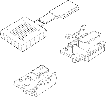
For a complete wiring diagram, refer to the Wiring Information.
-
When Monitored:
Engine cranking.
-
Set Condition:
No CKP signal is present during engine cranking and at least eight Camshaft Position Sensor signals have occurred. One Trip Fault. Three good trips to turn off the MIL. If the vehicle is equipped with the stop/start feature, the system will be disabled when this DTC is active.
Possible Causes |
|---|
| 5-VOLT SUPPLY CIRCUIT SHORTED TO VOLTAGE |
| 5-VOLT SUPPLY CIRCUIT SHORTED TO GROUND |
| 5-VOLT SUPPLY CIRCUIT SHORTED TO THE CKP SENSOR GROUND CIRCUIT |
| 5-VOLT SUPPLY CIRCUIT OPEN/HIGH RESISTANCE |
| CKP SIGNAL CIRCUIT SHORTED TO VOLTAGE |
| CKP SIGNAL CIRCUIT SHORTED TO GROUND |
| CKP SIGNAL CIRCUIT SHORTED TO THE CKP SENSOR GROUND CIRCUIT |
| CKP SIGNAL CIRCUIT OPEN/HIGH RESISTANCE |
| CKP SENSOR GROUND CIRCUIT OPEN/HIGH RESISTANCE |
| CRANKSHAFT POSITION SENSOR |
| POWERTRAIN CONTROL MODULE (PCM) |
Always perform the Pre-Diagnostic Troubleshooting procedure before proceeding. (Refer to 28 - DTC-Based Diagnostics/MODULE, Powertrain Control (PCM) - Standard Procedure).
| 1. | Check for any applicable TSBs that may apply for this issue. |
Were any TSBs applicable?
Yes
- Perform the applicable TSB. Erase the DTC and perform the verification test.
- Perform the POWERTRAIN VERIFICATION TEST. (Refer to 28 - DTC-Based Diagnostics/MODULE, Powertrain Control (PCM) - Standard Procedure).
No
- Go To 2
| NOTE: | Diagnose and repair any 5-Volt reference DTCs before continuing with this test procedure. |
| 1. | Turn the ignition on. |
| 2. | Read and copy the DTC’s and Freeze Frame Data. |
| 3. | Start the engine, or crank the engine for 10 seconds. |
| NOTE: |
If the vehicle starts and runs, wiggle test the wiring and see if problem duplicates or the fault sets. |
Is the status Active for this DTC?
Yes
- Go To 5
No
- Go To 3
3. WIRE HARNESS/CKP SENSOR INSPECTION
| 1. | Turn the ignition off. |
| 2. | Disconnect the harness connectors at the PCM and Crank Sensor and inspect for wire chaffing or rub conditions, terminals pushed out on the wiring connector, bent terminals at the PCM and Crank Sensor, water in the connector cavities, presence of corrosion on the terminals of the connectors or components. |
| 3. | Visually inspect the mounting area of Crank Sensor for debris/damage or a loose sensor. Remove the Crank Sensor and inspect the end of the sensor for signs of damage or debris. Rotate the engine and if possible, inspect the target wheel for any signs of damage. Reinstall the Crank Sensor and ensure that the sensor is properly installed and torqued to proper specification. |
| NOTE: |
Due to the fact that this DTC is set by an intermittent loss of the signal, the most likely cause is a poor connection at the Crank Sensor or PCM terminals, or a poor signal between the Crank Sensor and target wheel. Because of this, unplugging and reconnecting the harness connectors, or repositioning the Crank Sensor will often repair the condition that set the DTC. |
Were any problems found?
Yes
- Perform the appropriate repair.
- Perform the POWERTRAIN VERIFICATION TEST. (Refer to 28 - DTC-Based Diagnostics/MODULE, Powertrain Control (PCM) - Standard Procedure).
No
- Go To 4
4. CHECK THE VEHICLE’S REPAIR HISTORY
| 1. | Check the history of the vehicle for previous crank sensor related DTCs within the past 90 days. |
Did the repair history show that the vehicle was in dealership for a crank sensor fault within the past 90 days?
Yes
- Replace the Crank Sensor in accordance with the service information.
- Perform the POWERTRAIN VERIFICATION TEST. (Refer to 28 - DTC-Based Diagnostics/MODULE, Powertrain Control (PCM) - Standard Procedure).
No
- Test complete. Reconnect the harness connectors, and erase the DTC. The most likely cause was a poor connection at one of the harness connectors. Verify the DTC does not return.
- Perform the POWERTRAIN VERIFICATION TEST. (Refer to 28 - DTC-Based Diagnostics/MODULE, Powertrain Control (PCM) - Standard Procedure).
5. CHECK THE (F855) 5-VOLT SUPPLY CIRCUIT VOLTAGE
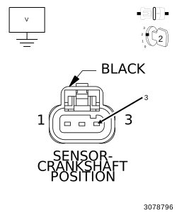 |
| 1. | Turn the ignition off. |
| 2. | Disconnect the CKP Sensor harness connector. |
| 3. | Turn the ignition on. |
| 4. | Measure the voltage of the (F855) 5-Volt Supply circuit at the CKP Sensor harness connector. |
Is the voltage between 4.8 and 5.2 volts?
Yes
- Go To 6
No, voltage is below 4.8 volts:
- Repair the 5-Volt Supply circuit for an open or short to ground.
- Perform the POWERTRAIN VERIFICATION TEST. (Refer to 28 - DTC-Based Diagnostics/MODULE, Powertrain Control (PCM) - Standard Procedure).
No, voltage is above 5.2 volts:
- Repair the 5-Volt Supply circuit for a short to voltage.
- Perform the POWERTRAIN VERIFICATION TEST. (Refer to 28 - DTC-Based Diagnostics/MODULE, Powertrain Control (PCM) - Standard Procedure).
6. CHECK THE (K24) CKP SIGNAL CIRCUIT VOLTAGE
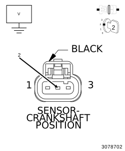 |
| 1. | Measure the voltage of the (K24) CKP Signal circuit at the CKP Sensor harness connector. |
Is the voltage between 4.8 and 5.2 volts?
Yes
- Go To 7
No
- Go To 9
7. CHECK THE (K925) SENSOR GROUND CIRCUIT FOR AN OPEN/HIGH RESISTANCE
| 1. | Turn the ignition off. |
| 2. | Disconnect the PCM C2 harness connector. |
Do not probe the PCM harness connectors. Probing the PCM harness
connectors will damage the PCM terminals resulting in poor terminal
to pin connection. Install the GPEC Diagnostic Adaptor to perform
the diagnosis.
CAUTION:
| 3. | Connect the Adapter, GPEC Diagnostic 10436 . |
| 4. | Measure the resistance of the (K925) Sensor ground circuit from the CKP Sensor harness connector to the GPEC Adaptor. |
Is the resistance below 5.0 Ohms?
Yes
- Go To 8
No
- Repair the (K925) Sensor ground circuit for an open or high resistance.
- Perform the POWERTRAIN VERIFICATION TEST. (Refer to 28 - DTC-Based Diagnostics/MODULE, Powertrain Control (PCM) - Standard Procedure).
8. TONE WHEEL/PULSE RING INSPECTION
| 1. | Turn the ignition off. |
| 2. | Disconnect the battery ground cable. |
| 3. | Remove the CKP Sensor. |
| 4. | Visually inspect the sensor mounting location for damage, foreign material. |
| 5. | Rotate the engine and if possible inspect the target wheel for any signs of damage. |
Were any problems found?
Yes
- Repair Issues in mounting location. Repair or replace the Tone Wheel / Pulse Ring as necessary.
- Perform the POWERTRAIN VERIFICATION TEST. (Refer to 28 - DTC-Based Diagnostics/MODULE, Powertrain Control (PCM) - Standard Procedure).
No
- Replace the Crank Position Sensor in accordance with the service information.
- Perform the POWERTRAIN VERIFICATION TEST. (Refer to 28 - DTC-Based Diagnostics/MODULE, Powertrain Control (PCM) - Standard Procedure).
9. CHECK THE (K24) CKP SIGNAL CIRCUIT FOR A SHORT TO GROUND
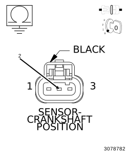 |
| 1. | Turn the ignition off. |
| 2. | Disconnect the PCM C2 harness connector. |
| 3. | Measure the resistance between ground and the (K24) CKP Signal circuit at the Crankshaft Position Sensor harness connector. |
Is the resistance above 10K Ohms?
Yes
- Go To 10
No
- Repair the (K24) CKP Signal circuit for a short to ground.
- Perform the POWERTRAIN VERIFICATION TEST. (Refer to 28 - DTC-Based Diagnostics/MODULE, Powertrain Control (PCM) - Standard Procedure).
10. CHECK THE (K24) CKP SIGNAL CIRCUIT FOR AN OPEN/HIGH RESISTANCE
| 1. | Turn the ignition off. |
Do not probe the PCM harness connectors. Probing the PCM harness
connectors will damage the PCM terminals resulting in poor terminal
to pin connection. Install the GPEC Diagnostic Adaptor to perform
the diagnosis.
CAUTION:
| 2. | Connect the Adapter, GPEC Diagnostic 10436 . |
| 3. | Measure the resistance of the (K24) CKP Signal circuit between the CKP Sensor harness connector to the GPEC Adaptor. |
Is the resistance below 5.0 Ohms?
Yes
- Go To 11
No
- Repair the (K24) CKP Signal circuit for an open or high resistance.
- Perform the POWERTRAIN VERIFICATION TEST. (Refer to 28 - DTC-Based Diagnostics/MODULE, Powertrain Control (PCM) - Standard Procedure).
11. POWERTRAIN CONTROL MODULE (PCM)
| 1. | Using the wiring diagram/schematic as a guide, inspect the wiring and connectors between the Crankshaft Position Sensor and the Powertrain Control Module (PCM). |
| 2. | Look for any chafed, pierced, pinched, or partially broken wires. |
| 3. | Look for broken, bent, pushed out or corroded terminals. Verify that there is good pin to terminal contact in the CKP Sensor and Powertrain Control Module connectors. |
| 4. | Monitor the scan tool data relative to this circuit and wiggle test the wiring and connectors. |
| 5. | Look for the data to change or for the DTC to reset during the wiggle test. |
| NOTE: |
Due to the fact that this DTC is set by an intermittent loss of the signal, the most likely cause is a poor connection at the Crank Sensor or PCM terminals, or a poor signal between the Crank Sensor and target wheel. Because of this, unplugging and reconnecting the harness connectors, or repositioning the Crank Sensor will often repair the condition that set the DTC. |
Were any problems found?
Yes
- Perform the appropriate repair.
- Perform the POWERTRAIN VERIFICATION TEST. (Refer to 28 - DTC-Based Diagnostics/MODULE, Powertrain Control (PCM) - Standard Procedure).
No
- Replace and program the Powertrain Control Module (PCM) in accordance with the service information. (Refer to 08 - Electrical/8E - Electronic Control Modules/MODULE, Powertrain Control - Removal) .
- Perform the POWERTRAIN VERIFICATION TEST. (Refer to 28 - DTC-Based Diagnostics/MODULE, Powertrain Control (PCM) - Standard Procedure).