P0443-EVAP PURGE SOLENOID CIRCUIT
For a complete wiring diagram, refer to the Wiring Information.
-
When Monitored:
The ignition on or engine running. Battery voltage greater than 10 Volts.
-
Set Condition:
The Powertrain Control Module (PCM) will set a trouble code if the actual state of the solenoid does not match the intended state. One Trip Fault. Three good trips to turn off the MIL.
Possible Causes |
|---|
| (K52) EVAP PURGE CONTROL CIRCUIT SHORTED TO VOLTAGE |
| (K70) EVAP PURGE SOLENOID SIGNAL CIRCUIT SHORTED TO VOLTAGE |
| (K52) EVAP PURGE SOLENOID CONTROL CIRCUIT SHORTED TO GROUND |
| EXCESSIVE RESISTANCE IN THE (K52) EVAP PURGE CONTROL CIRCUIT |
| EXCESSIVE RESISTANCE IN THE (K70) EVAP PURGE SOLENOID SIGNAL CIRCUIT |
| EVAP PURGE SOLENOID |
| POWERTRAIN CONTROL MODULE (PCM) |
Always perform the Pre-Diagnostic Troubleshooting procedure before proceeding. (Refer to 28 - DTC-Based Diagnostics/MODULE, Powertrain Control (PCM) - Standard Procedure).
1. VEHICLE HISTORY AND SERVICE BULLETIN INVESTIGATION
| 1. | Ignition on, engine not running. |
| 2. | With the scan tool, select View DTCs. Record the related Freeze Frame data if any DTCs are present. |
Choose the following scenario that best applies.
The service bulletin repaired the customer's complaint.
A DTC is present, no service bulletins apply or the service bulletin didn't repair the customer's complaint.
- Go To 2
| 1. | Ignition on, engine not running. |
| 2. | With the scan tool, Select View DTCs. |
Is the DTC Active at this time?
Yes
- Go To 3
No
- Perform the INTERMITTENT CONDITION diagnostic procedure. (Refer to 28 - DTC-Based Diagnostics/MODULE, Powertrain Control (PCM) - Standard Procedure).
3. (K52) EVAP PURGE CONTROL CIRCUIT SHORTED TO VOLTAGE
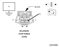 |
| 1. | Turn the ignition off. |
| 2. | Disconnect the Evap Purge Solenoid harness connector. |
| 3. | Disconnect the PCM harness connector. |
| 4. | Ignition on, engine not running. |
| 5. | Measure the voltage of the (K52) Evap Purge Control circuit in the Evap Purge Solenoid harness connector. |
Is there any voltage present?
Yes
- Repair the short to voltage in the (K52) Evap Purge Control circuit.
- Perform the POWERTRAIN VERIFICATION TEST. (Refer to 28 - DTC-Based Diagnostics/MODULE, Powertrain Control (PCM) - Standard Procedure).
No
-
Go To 4
4. (K70) EVAP PURGE RETURN CIRCUIT SHORTED TO VOLTAGE
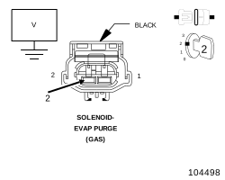 |
| 1. | Measure the voltage of the (K70) Evap Purge Return circuit in the Evap Purge Solenoid harness connector. |
Is there any voltage present?
Yes
- Repair the short to voltage in the (K70) Evap Purge Return circuit.
- Perform the POWERTRAIN VERIFICATION TEST. (Refer to 28 - DTC-Based Diagnostics/MODULE, Powertrain Control (PCM) - Standard Procedure).
No
-
Go To 5
5. (K52) EVAP PURGE CONTROL CIRCUIT SHORTED TO GROUND
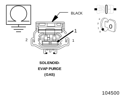 |
| 1. | Turn the ignition off. |
| 2. | Measure the resistance between ground and the (K52) Evap Purge Control circuit in the Evap Purge Solenoid harness connector. |
Is the resistance below 100 Ohms?
Yes
- Repair the (K52) Evap Purge Control circuit for a short to ground.
- Perform the POWERTRAIN VERIFICATION TEST. (Refer to 28 - DTC-Based Diagnostics/MODULE, Powertrain Control (PCM) - Standard Procedure).
No
- Go To 6
6. (K52) EVAP PURGE SOLENOID CONTROL CIRCUIT OPEN
| 1. | Measure the resistance of the (K52) Evap Purge Solenoid Control circuit from the Evap Purge Solenoid harness connector to the appropriate terminal of PCM harness connector . |
Is the resistance below 5.0 Ohms?
Yes
- Go To 7
No
- Repair the open in the (K52) Evap Purge Solenoid Control circuit.
- Perform the POWERTRAIN VERIFICATION TEST. (Refer to 28 - DTC-Based Diagnostics/MODULE, Powertrain Control (PCM) - Standard Procedure).
7. (K70) EVAP PURGE SOLENOID SIGNAL CIRCUIT OPEN
| 1. | Measure the resistance of the (K70) Evap Purge Solenoid Signal circuit from the Evap Purge Solenoid harness connector to the appropriate terminal of PCM harness connector. |
Is the resistance below 5.0 Ohms?
Yes
- Go To 8
No
- Repair the open in the (K70) Evap Purge Solenoid Signal circuit.
- Perform the POWERTRAIN VERIFICATION TEST. (Refer to 28 - DTC-Based Diagnostics/MODULE, Powertrain Control (PCM) - Standard Procedure).
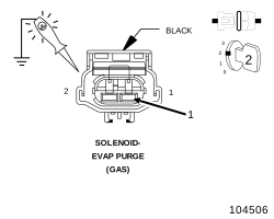 |
| 1. | Connect the PCM harness connector. |
| 2. | Ignition on, engine not running. |
| 3. | Using a 12-volt test light connected to ground, check the (K52) Evap Purge Control circuit in the Evap Purge Solenoid harness connector. |
| 4. | With the scan tool, actuate the Evap Purge Solenoid control to the ON (100%) position. |
| NOTE: | The DTC needs to be cleared before actuating the Purge Solenoid, if the DTC is not cleared, the Solenoid may not be allowed to actuate. |
| NOTE: | The test light should be illuminated and bright proportional to the maximum duty cycle allowed by the scan tool. For example, if the scan tool allows 100% actuation, the brightness should be as bright as a direct connection to the battery. If the scan tool allows a maximum 25% actuation, the brightness should be 25% as bright as a direct connection to the battery. |
Does the test light illuminate accordingly during the actuation?
Yes
- Verify that there is good pin to terminal contact in the Solenoid and the Powertrain Control Module harness connectors. Replace the Evap Purge Solenoid if no problems were found in the connectors.
- Perform the POWERTRAIN VERIFICATION TEST. (Refer to 28 - DTC-Based Diagnostics/MODULE, Powertrain Control (PCM) - Standard Procedure).
No
-
Go To 9
9. POWERTRAIN CONTROL MODULE (PCM)
| 1. | Using the wiring diagram/schematic as a guide, inspect the wiring and connectors between the Evap Purge Solenoid Assembly, ESIM switch and the Powertrain Control Module (PCM). |
| 2. | Look for any chafed, pierced, pinched or partially broken wires. |
| 3. | Look for broken, bent, pushed out or corroded terminals. Verify that there is good pin to terminal contact in the Switch, Solenoid and the Powertrain Control Module harness connectors. |
| 4. | Perform any Technical Service Bulletins that may apply. |
Were there any problems found?
Yes
- Repair as necessary.
- Perform the POWERTRAIN VERIFICATION TEST. (Refer to 28 - DTC-Based Diagnostics/MODULE, Powertrain Control (PCM) - Standard Procedure).
No
- Replace and program the Powertrain Control Module in accordance with the Service Information. (Refer to 08 - Electrical/8E - Electronic Control Modules/MODULE, Powertrain Control - Removal) .
- Perform the POWERTRAIN VERIFICATION TEST. (Refer to 28 - DTC-Based Diagnostics/MODULE, Powertrain Control (PCM) - Standard Procedure).