P0020-BANK 2 CAMSHAFT 1 POSITION ACTUATOR CIRCUIT OPEN
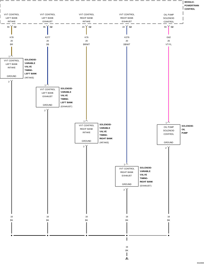
For a complete wiring diagram refer to the Wiring Information.
 |
Theory of Operation
 |
| NOTE: |
The CMP Sensor is a dual read sensor reading both camshafts of it's correlating bank. |
|
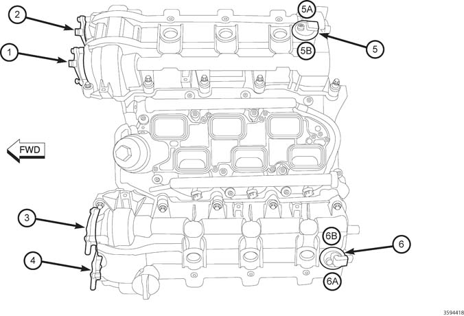
3.2L/3.6L VVT Component Locations |
|
|---|---|
|
CALLOUT |
DESCRIPTION |
|
1 |
VVT Actuator Bank 1 Position 1 (Intake) |
|
2 |
VVT Actuator Bank 1 Position 2 (Exhaust) |
|
3 |
VVT Actuator Bank 2 Position 1 (Intake) |
|
4 |
VVT Actuator Bank 2 Position 2 (Exhaust) |
|
5 |
Bank 1 Camshaft Sensor |
|
5A |
CMP Bank 1 Sensor 1 (Exhaust) |
|
5B |
CMP Bank 1 Sensor 2 (Intake) |
|
6 |
Bank 2 Camshaft Sensor |
|
6A |
CMP Bank 2 Sensor 1 (Exhaust) |
|
6B |
CMP Bank 2 Sensor 2 (Intake) |
Variable Valve Timing (VVT) allows the Powertrain Control Module (PCM) to monitor and adjust the position of each Camshaft, based on desired torque levels and engine operating conditions. The PCM controls solenoid operated control valves located on the front of the engine. There is one solenoid for each Camshaft, used to direct oil pressure to hydraulic actuators mounted between each Camshaft and its driving sprocket. The oil pressure alters the angular position or phasing of each Camshaft relative to Crankshaft rotation. A sensor is used to monitor the position of each Camshaft.
There are four separate Camshafts that the Powertrain Control Module (PCM) requires positional information from. There are two Camshaft Position (CMP) Sensors with each CMP Sensor consisting of four circuits. The sensors are located at the top rear of each valve cover. On the end of each Camshaft is a magnetic encoder that is programmed with a magnetic pattern. The PCM provides a 5-Volt supply and a sensor ground circuit to the CMP Sensor and the CMP Sensor provides two Camshaft positional signals, the intake and exhaust camshaft position, to the PCM. The sensor detects the magnetically encoded information, a series of magnetic peaks and valleys, from the encoder. As each Camshaft rotates, the magnetic encoded pattern passes by the CMP Sensor creating a changing magnetic field at the sensor face. The changing magnetic field is interpreted by the sensor electronics and a digital output, ON/OFF or HIGH/LOW pattern, is produced. The length of the pulse width generated by the CMP varies in size based on the velocity of the Camshaft. The PCM decodes the digital pattern to identify the Camshaft position. The information from each individual Camshaft along with the Crankshaft information is used to control and sequence the Variable Valve Timing (VVT) system and fuel injection events.
-
When Monitored:
Variable Valve Timing (VVT) rationality is monitored under the following conditions: (1) Cam phasing is commanded off of the default (lockpin) position; (2) Oil temperature is between -12°C to 139°C (10°F to 282°F); (3) Battery voltage is greater than 10.0 Volts; (3) Engine speed is at least 650 to 1400 RPM, depending on oil temperature; (4) No CMP Sensor, CKP Sensor or OBDI plausibility errors. Before VVT can be enabled, reference adaptation must be completed.
-
Set Condition:
The PCM detects that the VVT Intake Solenoid 2/1 Driver circuit is open.
Possible Causes |
|---|
| VVT INTAKE SOLENOID 2/1 DRIVER CIRCUIT SHORTED TO GROUND |
| VVT INTAKE SOLENOID 2/1 DRIVER CIRCUIT SHORTED TO VOLTAGE |
| VVT INTAKE SOLENOID 2/1 DRIVER CIRCUIT OPEN OR HIGH RESISTANCE |
| GROUND CIRCUIT FOR THE VVT INTAKE SOLENOID 2/1 OPEN OR HIGH RESISTANCE |
| VVT INTAKE SOLENOID 2/1 |
| POWERTRAIN CONTROL MODULE (PCM) |
Always perform the Pre-Diagnostic Troubleshooting procedure before proceeding. (Refer to 28 - DTC-Based Diagnostics/MODULE, Powertrain Control (PCM) - Standard Procedure).
| 1. | Start the engine and allow it to reach normal operating temperature. |
When the engine is operating, do
not stand in direct line with the fan. Do not put your hands near
the pulleys, belts or fan. Do not wear loose clothing. Failure to
follow these instructions may result in possible serious or fatal
injury.
WARNING:
| 2. | With the scan tool, clear DTCs in the Powertrain Control Module (PCM). |
| 3. | Test drive the vehicle under the conditions in which the DTC is monitored, as outlined above. |
| 4. | With the scan tool, select View DTCs. |
Is the DTC Active or Pending at this time?
Yes
- Go To 4
No
- Perform the INTERMITTENT CONDITION diagnostic procedure. (Refer to 28 - DTC-Based Diagnostics/MODULE, Powertrain Control (PCM) - Standard Procedure).
2. CHECK THE (K78) VVT INTAKE SOLENOID 2/1 DRIVER CIRCUIT FOR A SHORT TO VOLTAGE
| 1. | Turn the ignition off. |
| 2. | Disconnect the VVT Intake Solenoid 2/1 harness connector. |
| 3. | Turn the ignition on. |
| 4. | Measure the voltage of the (K78) VVT Intake Solenoid 2/1 Driver circuit at the VVT Intake Solenoid 2/1 harness connector. |
| NOTE: | The VVT Solenoid Driver circuit is a PWM circuit which will read approximately 8.8 volts with ignition on and the solenoid disconnected. |
Is the voltage equal to battery voltage?
Yes
- Repair the (K78) VVT Intake Solenoid 2/1 Driver circuit for a short to voltage.
- Perform the POWERTRAIN VERIFICATION TEST. (Refer to 28 - DTC-Based Diagnostics/MODULE, Powertrain Control (PCM) - Standard Procedure).
No
- Go To 3
3. CHECK THE (K78) VVT INTAKE SOLENOID 2/1 DRIVER CIRCUIT FOR A SHORT TO GROUND
| 1. | Turn the ignition off. |
| 2. | Disconnect the PCM C2 harness connector. |
| 3. | Measure the resistance between ground and the (K78) VVT Intake Solenoid 2/1 Driver circuit at the VVT Intake Solenoid 2/1 harness connector. |
Is the resistance above 10k Ohms?
Yes
- Go To 4
No
- Repair the (K78) VVT Exhaust Solenoid 2/1 Driver circuit for a short to ground.
- Perform the POWERTRAIN VERIFICATION TEST. (Refer to 28 - DTC-Based Diagnostics/MODULE, Powertrain Control (PCM) - Standard Procedure).
4. CHECK THE (K78) VVT INTAKE SOLENOID 2/1 DRIVER CIRCUIT FOR AN OPEN/HIGH RESISTANCE
Do not probe the PCM harness connectors. Probing the PCM harness
connectors will damage the PCM terminals resulting in poor terminal
to pin connection. Install the GPEC Diagnostic Adaptor to perform
the diagnosis.
CAUTION:
| 1. | Connect the Adapter, GPEC Diagnostic 10436 . |
| 2. | Measure the resistance of the (K78) VVT Intake Solenoid 2/1 Driver circuit between the VVT Intake Solenoid 2/1 harness connector and the GPEC Adaptor. |
Is the resistance below 5.0 Ohms?
Yes
- Go To 5
No
- Repair the (K78) VVT Intake Solenoid 2/1 Driver circuit for an open or high resistance.
- Perform the POWERTRAIN VERIFICATION TEST. (Refer to 28 - DTC-Based Diagnostics/MODULE, Powertrain Control (PCM) - Standard Procedure).
5. CHECK THE GROUND CIRCUIT FOR AN OPEN/HIGH RESISTANCE
| 1. | Measure the resistance between ground and the Ground circuit at the VVT Intake Solenoid 1/1 harness connector. |
Is the resistance below 5.0 Ohms?
Yes
- Go To 6
No
- Repair the Ground circuit for an open or high resistance.
- Perform the POWERTRAIN VERIFICATION TEST. (Refer to 28 - DTC-Based Diagnostics/MODULE, Powertrain Control (PCM) - Standard Procedure).
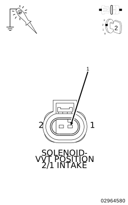
6. CHECK THE (K78) VVT INTAKE SOLENOID 2/1 DRIVER CIRCUIT ACTUATION
 |
| 1. | Connect the PCM C2 harness connector. |
| 2. | Turn the ignition on. |
| 3. | Using a 12-volt test light connected to ground, probe the (K78) VVT Intake Solenoid 2/1 Driver circuit in the VVT Intake Solenoid 2/1 harness connector. |
| NOTE: | The test light should be off unless you have a short to voltage, except for a brief period immediately after turning ignition on. |
| 4. | With the scan tool, actuate the VVT Intake Solenoid 2/1 to the ON (maximum) position. |
| NOTE: | The test light should be illuminated and bright. Compare the brightness to that of a direct connection to the battery. |
Is the test light illuminated and bright?
Yes
- Go To 7
No
- Go To 8
| 1. | Turn the ignition off. |
| 2. | Inspect the wiring and connectors between the VVT Intake Solenoid 2/1 and the Powertrain Control Module (PCM). |
| 3. | Verify that there is good pin to terminal contact in the VVT Intake Solenoid 2/1 and Powertrain Control Module harness connectors. |
| 4. | Look for any chafed, pierced, pinched or partially broken wires. |
| 5. | Look for broken, bent, pushed out or corroded terminals. |
| 6. | Look for signs of water intrusion past the connector seal. |
Were any problems found?
Yes
- Repair as necessary.
- Perform the POWERTRAIN VERIFICATION TEST. (Refer to 28 - DTC-Based Diagnostics/MODULE, Powertrain Control (PCM) - Standard Procedure).
No
- Replace the VVT Intake Solenoid 2/1 in accordance with the service information.
- Perform the POWERTRAIN VERIFICATION TEST. (Refer to 28 - DTC-Based Diagnostics/MODULE, Powertrain Control (PCM) - Standard Procedure).
8. POWERTRAIN CONTROL MODULE (PCM)
| 1. | Using the wiring diagram/schematic as a guide, inspect the wiring and connectors between the VVT Intake Solenoid 2/1 and the Powertrain Control Module (PCM). |
| 2. | Look for any chafed, pierced, pinched, or partially broken wires. |
| 3. | Look for broken, bent, pushed out or corroded terminals. |
| 4. | Perform any Technical Service Bulletins that may apply. |
Were any problems found?
Yes
- Repair as necessary.
- Perform the POWERTRAIN VERIFICATION TEST. (Refer to 28 - DTC-Based Diagnostics/MODULE, Powertrain Control (PCM) - Standard Procedure).
No
- Replace the Powertrain Control Module (PCM) in accordance with the service information. (Refer to 08 - Electrical/8E - Electronic Control Modules/MODULE, Powertrain Control - Removal) .
- Perform the POWERTRAIN VERIFICATION TEST. (Refer to 28 - DTC-Based Diagnostics/MODULE, Powertrain Control (PCM) - Standard Procedure).