P0129-BAROMETRIC PRESSURE OUT-OF-RANGE LOW
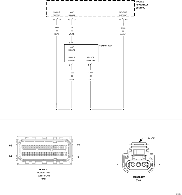 |
For a complete wiring diagram, refer to the Wiring Information.
Theory of operation
The Barometric Pressure (BARO) Sensor is the Manifold Absolute Pressure (MAP) Sensor which is a transducer that varies resistance according to changes in altitude and atmospheric conditions. The BARO reading, which is read the first few moments before engine cranking, gives the Powertrain Control Module (PCM) an indication of the current barometric pressure. The PCM uses this information to calculate fuel delivery. The PCM supplies 5 Volts to the MAP Sensor on a 5-Volt reference circuit and provides a ground on a low reference circuit. The MAP sensor provides a voltage signal to the PCM on a signal circuit relative to the pressure changes. The PCM monitors the stability of the BARO reading output by comparing successive samples.
-
When Monitored:
With the ignition key on. No Cam or Crank signal within 75 ms. Engine speed less than 250 RPM.
-
Set Condition:
The Powertrain Control Module (PCM) senses the voltage from the MAP sensor to be less than 2.2 Volts but above 0.04 of a Volt for 300 milliseconds. One Trip Fault. Three good trips to turn off the MIL. MIL is illuminated and the ETC lamp will flash.
Possible Causes |
|---|
| (F856) 5-VOLT SUPPLY CIRCUIT SHORTED TO VOLTAGE |
| (F856) 5-VOLT SUPPLY CIRCUIT OPEN |
| (F856) 5-VOLT SUPPLY CIRCUIT SHORTED TO GROUND |
| (K1) MAP SIGNAL CIRCUIT OPEN |
| (K1) MAP SIGNAL CIRCUIT SHORTED TO GROUND |
| (K1) MAP SIGNAL CIRCUIT SHORTED TO THE (K900) SENSOR GROUND |
| MAP SENSOR |
| POWERTRAIN CONTROL MODULE (PCM) |
Always perform the Pre-Diagnostic Troubleshooting procedure before proceeding. (Refer to 28 - DTC-Based Diagnostics/MODULE, Powertrain Control (PCM) - Standard Procedure).
1. ACTIVE DIAGNOSTIC TROUBLE CODE (DTC)
| 1. | Ignition on, engine not running. |
| 2. | With the scan tool, read the active DTCs. |
Is the DTC Active at this time.
Yes
- Go To 2
No
- Perform the INTERMITTENT CONDITION diagnostic procedure. (Refer to 28 - DTC-Based Diagnostics/MODULE, Powertrain Control (PCM) - Standard Procedure).
2. (F856) 5-VOLT SUPPLY CIRCUIT
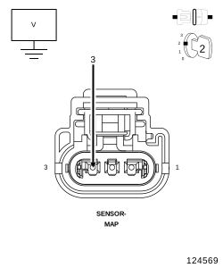 |
| 1. | Turn the ignition off. |
| 2. | Disconnect the MAP Sensor harness connector. |
| 3. | Ignition on, engine not running. |
| 4. | Measure the voltage on the (F856) 5-Volt Supply circuit in the MAP Sensor harness connector. |
Is the voltage between 4.5 to 5.2 Volts?
Yes
- Go To 3
No
-
Go To 7
| 1. | With the scan tool, monitor the MAP Sensor voltage with the Sensor harness connector disconnected. |
Is the voltage above 2.2 Volts?
Yes
- Verify that there is good pin to terminal contact in the MAP Sensor and Powertrain Control Module connectors. If OK, replace the MAP Sensor in accordance with the service information. (Refer to 14 - Fuel System/Fuel Injection/SENSOR, Manifold Air Pressure (MAP) - Removal).
- Perform the POWERTRAIN VERIFICATION TEST. (Refer to 28 - DTC-Based Diagnostics/MODULE, Powertrain Control (PCM) - Standard Procedure).
No
- Go To 4
4. (K1) MAP SIGNAL CIRCUIT OPEN
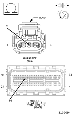 |
| 1. | Turn the ignition off. |
| 2. | Disconnect the PCM C2 harness connector. |
| 3. | Measure the resistance of the (K1) MAP Signal circuit from the MAP Sensor harness connector to the PCM C2 harness connector. |
Is the resistance below 5.0 Ohms?
Yes
- Go To 5
No
- Repair the open in the (K1) MAP Signal circuit.
-
Perform the POWERTRAIN VERIFICATION TEST. (Refer to 28 - DTC-Based Diagnostics/MODULE, Powertrain Control (PCM)
- Standard Procedure).
5. (K1) MAP SIGNAL CIRCUIT SHORTED TO THE (K900) SENSOR GROUND CIRCUIT
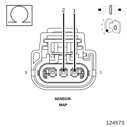 |
| 1. | Measure the resistance between the (K900) Sensor ground circuit and the (K1) MAP Signal circuit in the MAP Sensor harness connector. |
Is the resistance below 100 Ohms?
Yes
- Repair the short between the (K900) Sensor ground circuit and the (K1) MAP Signal circuit.
- Perform the POWERTRAIN VERIFICATION TEST. (Refer to 28 - DTC-Based Diagnostics/MODULE, Powertrain Control (PCM) - Standard Procedure).
No
-
Go To 6
6. (K1) MAP SIGNAL CIRCUIT SHORTED TO GROUND
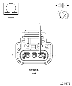 |
| 1. | Measure the resistance between ground and the (K1) MAP Signal circuit in the MAP Sensor harness connector. |
Is the resistance below 100 Ohms?
Yes
- Repair the short to ground in the (K1) MAP Signal circuit.
- Perform the POWERTRAIN VERIFICATION TEST. (Refer to 28 - DTC-Based Diagnostics/MODULE, Powertrain Control (PCM) - Standard Procedure).
No
-
Go To 10
7. (F856) 5-VOLT SUPPLY CIRCUIT SHORTED TO VOLTAGE
|
| 1. | Turn the ignition off. |
| 2. | Disconnect the PCM C2 harness connector. |
| 3. | Ignition on, engine not running. |
| 4. | Measure the voltage on the (F856) 5-Volt Supply circuit in the MAP Sensor harness connector. |
Is there any voltage present?
Yes
- Repair the short to voltage in the (F856) 5-Volt Supply circuit.
- Perform the POWERTRAIN VERIFICATION TEST. (Refer to 28 - DTC-Based Diagnostics/MODULE, Powertrain Control (PCM) - Standard Procedure).
No
-
Go To 8
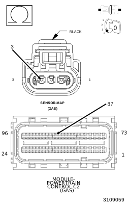
8. (F856) 5-VOLT SUPPLY CIRCUIT OPEN
 |
| 1. | Turn the ignition off. |
| 2. | Measure the resistance of the (F856) 5-Volt Supply circuit from the MAP Sensor harness connector to the PCM C2 harness connector. |
Is the resistance below 5.0 Ohms?
Yes
- Go To 9
No
- Repair the open in the (F856) 5-Volt Supply circuit.
-
Perform the POWERTRAIN VERIFICATION TEST. (Refer to 28 - DTC-Based Diagnostics/MODULE, Powertrain Control (PCM)
- Standard Procedure).
9. (F856) 5-VOLT SUPPLY CIRCUIT SHORTED TO GROUND
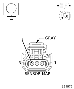 |
| 1. | Measure the resistance between ground and the (F856) 5-Volt Supply circuit in the MAP Sensor harness connector. |
Is the resistance below 100 Ohms?
Yes
- Repair the short to ground in the (F856) 5-Volt Supply circuit.
- Perform the POWERTRAIN VERIFICATION TEST. (Refer to 28 - DTC-Based Diagnostics/MODULE, Powertrain Control (PCM) - Standard Procedure).
No
-
Go To 10
10. POWERTRAIN CONTROL MODULE (PCM)
| 1. | Using the wiring diagram/schematic as a guide, inspect the wiring and connectors between the MAP Sensor and the Powertrain Control Module (PCM). |
| 2. | Look for any chafed, pierced, pinched or partially broken wires. |
| 3. | Look for broken, bent, pushed out or corroded terminals. Verify that there is good pin to terminal contact in the MAP Sensor and Powertrain Control Module connectors. |
| 4. | Perform any Technical Service Bulletins that may apply. |
Were there any problems found?
Yes
- Repair as necessary.
- Perform the POWERTRAIN VERIFICATION TEST. (Refer to 28 - DTC-Based Diagnostics/MODULE, Powertrain Control (PCM) - Standard Procedure).
No
- Replace and program the Powertrain Control Module in accordance with the Service Information. (Refer to 08 - Electrical/8E - Electronic Control Modules/MODULE, Powertrain Control - Removal) .
- Perform the POWERTRAIN VERIFICATION TEST. (Refer to 28 - DTC-Based Diagnostics/MODULE, Powertrain Control (PCM) - Standard Procedure).