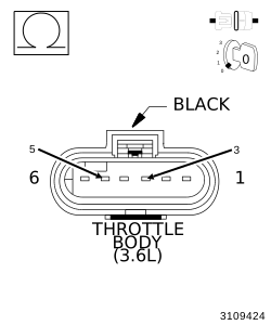
For a complete wiring diagram, refer to the Wiring Information.
Theory of operation
The Electronic Throttle Control (ETC) system uses two Throttle Position Sensors (TPS) to monitor the throttle blade position. The Throttle Position Sensors 1 and 2 are located within the Throttle Body assembly. Each sensor has a 5-volt reference circuit, a low reference circuit, and a signal circuit. Processors are also used to monitor the ETC system data. The processors are located within the Powertrain Control Module (PCM). Each signal circuit provides the processors with a signal voltage proportional to throttle blade movement. The processors share and monitor data to verify that the indicated TPS calculation is correct.
When Monitored:
Ignition on and No MAP Sensor DTCs set.
Set Condition:
TP Sensor signals do not correlate to the MAP Sensor signal. Two Trip Fault. ETC light will illuminate. P2135 should set with this code also.
Possible Causes
EXCESSIVE RESISTANCE IN THE (K22) TP SENSOR NO.1
EXCESSIVE RESISTANCE IN THE (K122) TP SENSOR NO.2 SIGNAL CIRCUIT
EXCESSIVE RESISTANCE IN THE (F855) 5-VOLT SUPPLY CIRCUIT
EXCESSIVE RESISTANCE IN THE (K922) TP SENSOR RETURN CIRCUIT
(K22) TP SENSOR NO.1 SIGNAL CIRCUIT SHORTED TO THE (K122) TP SENSOR NO.2 SIGNAL CIRCUIT
2.
EXCESSIVE RESISTANCE IN THE (K122) TP SENSOR NO.2 SIGNAL CIRCUIT
1.
Turn the ignition off.
2.
Disconnect the PCM C2 harness connector.
3.
Using a Voltmeter, perform a voltage drop test. Back probe the (K122) TP Sensor No.2 Signal circuit at the Throttle Body harness connector and the PCM C2 harness connector. Make sure the Voltmeter leads are connected so a positive polarity is displayed on the Voltmeter.
WARNING:
When the engine is operating, do
not stand in direct line with the fan. Do not put your hands near
the pulleys, belts or fan. Do not wear loose clothing. Failure to
follow these instructions may result in possible serious or fatal
injury.
4.
Start the engine and allow it to reach normal operating temperature.
3.
EXCESSIVE RESISTANCE IN THE (K22) TP SENSOR NO.1 SIGNAL CIRCUIT
1.
Turn the ignition off.
2.
Move the Voltmeter leads to back probe the (K22) TP Sensor No.1 Signal circuit at the Throttle Body harness connector and the PCM C2 harness connector. Make sure the Voltmeter leads are connected so a positive polarity is displayed on the Voltmeter.
WARNING:
When the engine is operating, do
not stand in direct line with the fan. Do not put your hands near
the pulleys, belts or fan. Do not wear loose clothing. Failure to
follow these instructions may result in possible serious or fatal
injury.
3.
Start the engine and allow it to reach normal operating temperature.
4.
EXCESSIVE RESISTANCE IN THE (F855) 5-VOLT SUPPLY CIRCUIT
1.
Turn the ignition off.
2.
Move the Voltmeter leads to back probe the (F855) 5-volt Supply circuit at the Throttle Body harness connector and the PCM C2 harness connector. Make sure the Voltmeter leads are connected so a positive polarity is displayed on the Voltmeter.
WARNING:
When the engine is operating, do
not stand in direct line with the fan. Do not put your hands near
the pulleys, belts or fan. Do not wear loose clothing. Failure to
follow these instructions may result in possible serious or fatal
injury.
3.
Start the engine and allow it to reach normal operating temperature.
5.
EXCESSIVE RESISTANCE IN THE (K922) TP SENSOR RETURN CIRCUIT
1.
Turn the ignition off.
2.
Move the Voltmeter leads to back probe the (K922) TP Sensor Return circuit at the Throttle Body harness connector and the PCM C2 harness connector. Make sure the Voltmeter leads are connected so a positive polarity is displayed on the Voltmeter.
WARNING:
When the engine is operating, do
not stand in direct line with the fan. Do not put your hands near
the pulleys, belts or fan. Do not wear loose clothing. Failure to
follow these instructions may result in possible serious or fatal
injury.
3.
Start the engine and allow it to reach normal operating temperature.
6.
(K22) TP SENSOR NO.1 SIGNAL CIRCUIT SHORTED TO THE (K122) TP SENSOR NO.2 SIGNAL CIRCUIT
1.
Measure the resistance between the (K22) TP Sensor No.1 Signal circuit and the (K122) TP Sensor No.2 Signal circuit at the Throttle Body harness connector.
Is the resistance below 5.0 Ohms?
Yes
Repair the short between the (K122) TP Sensor No.2 Signal circuit and the (K22) TP Sensor No.1 Signal circuit.
Using the scan tool, monitor the TP Sensor No.1 and No.2 voltage.
5.
Connect a jumper wire between the (K922) TP Sensor Return circuit and the (K22) TP Sensor No.1 Signal circuit.
NOTE:
TP Sensor No.1 voltage should change from approximately 4.7 volts to 0.3 volt.
6.
For TP Sensor No.2, connect a jumper wire between (F855) 5-Volt supply circuit and the (K122) TP Sensor No.2 Signal circuit.
NOTE:
TP Sensor No.2 voltage should change from approximately 0 volts to 5.0 volts.
Is the voltage reading within the listed specification with the jumper wire installed?
Yes
Verify that there is good pin to terminal contact in the Throttle Body and Powertrain Control Module connectors. If OK, replace the Throttle Body Assembly. Disconnect the Battery when replacing the Throttle Body Assembly. After installation is complete, using a scan tool select the ETC RELEARN function. (Refer to 14 - Fuel System/Fuel Injection/THROTTLE BODY - Removal)
.
Using the wiring diagram/schematic as a guide, inspect the wiring and connectors between the Throttle Body and the Powertrain Control Module (PCM).
2.
Look for any chafed, pierced, pinched, or partially broken wires.
3.
Look for broken, bent, pushed out or corroded terminals. Verify that there is good pin to terminal contact in the Throttle Body and Powertrain Control Module connectors.
4.
Perform any Technical Service Bulletins that may apply.
Verify that there is good pin to terminal contact in the Throttle Body and Powertrain Control Module connectors. If OK, replace the Throttle Body Assembly. Disconnect the Battery when replacing the Throttle Body Assembly. After installation is complete, using a scan tool select the ETC RELEARN function. (Refer to 14 - Fuel System/Fuel Injection/THROTTLE BODY - Removal)
.