P0440-GENERAL EVAP SYSTEM FAILURE
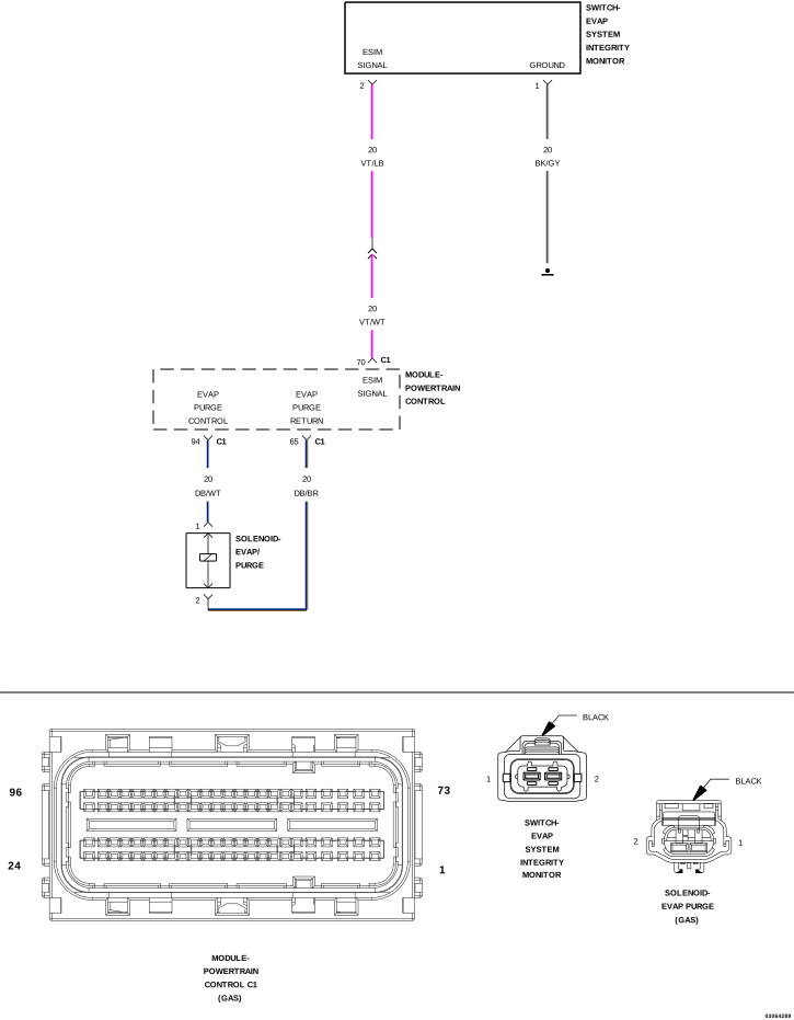
For a complete wiring diagram, refer to the Wiring Information.
 |
Theory of Operation
 |
|
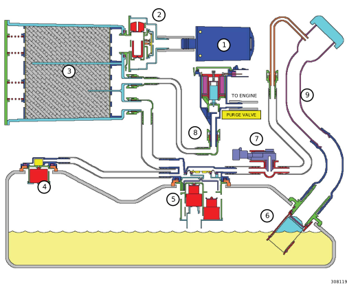
EVAP SYSTEM COMPONENTS |
|
|---|---|
|
CALLOUT |
DESCRIPTION |
|
1 |
Filter |
|
2 |
ESIM Switch |
|
3 |
Evaporative Canister |
|
4 |
Fuel Tank Vent (Check Valve) |
|
5 |
Control Valve |
|
6 |
Inlet Check Valve |
|
7 |
Fuel Tank Pressure Sensor |
|
8 |
To Purge System |
|
9 |
Fuel Fill Tube |
The Powertrain Control Module (PCM) detected that the Evap system was unable to achieve or maintain vacuum during the test period or the system was not able to close the ESIM switch when vacuum was present.
-
When Monitored:
Engine running after a cold start with the difference between ECT and AAT is less than 10°C (19 F). Fuel Level between 12% and 88% full. Manifold vacuum greater than a calculated minimum value. Ambient Temperature between 4°C and 35°C (40°F and 95°F).
-
Set Condition:
When the monitor conditions are met, the Powertrain Control Module (PCM) will ramp in purge flow. If the PCM does not sense an ESIM Switch closure after a calculated amount of purge flow accumulation, an error is detected. Two Trip Fault. Three good trips to turn off the MIL.
Possible Causes |
|---|
| EVAP PURGE SOLENOID VACUUM SUPPLY |
| EVAP PURGE HOSE/TUBE AND FRESH AIR FILTER OBSTRUCTION |
| GROUND CIRCUIT OPEN |
| ESIM ORIENTATION OR INSTALLED INCORRECTLY |
| ESIM SIGNAL CIRCUIT OPEN |
| EVAPORATIVE EMISSION LEAK |
| EVAPORATIVE SYSTEM INTEGRITY MONITOR SWITCH |
| EVAP PURGE SOLENOID |
| POWERTRAIN CONTROL MODULE (PCM) |
Always perform the Pre-Diagnostic Troubleshooting procedure before proceeding. (Refer to 28 - DTC-Based Diagnostics/MODULE, Powertrain Control (PCM) - Standard Procedure).
1. VEHICLE HISTORY AND SERVICE BULLETIN INVESTIGATION
| 1. | Ignition on, engine not running. |
| 2. | With the scan tool, select View DTCs. Record the related Freeze Frame data if any DTCs are present. |
Choose the following scenario that applies.
The service bulletin repaired the customer's complaint.
A DTC is present, no service bulletins apply or the service bulletin didn't repair the customer's complaint.
- Go To 2
| NOTE: | Allow the vehicle to reach ambient temperature before continuing with this procedure. |
| NOTE: | A loose gas cap could have caused this DTC to set. Make sure the gas cap is tight and in good condition. |
| NOTE: | If the customer is experiencing an early fuel shut off during the fuel filling process along with P0440, P0441 and P0452 setting, you need to check for restrictions in the Evaporative Purge tubes/hoses as well as the Fresh Air Filter before continuing. |
| 1. | Using the scan tool, perform the ESIM FORCED MONITOR TEST. Allow the test to complete. |
| 2. | Using the scan tool, read DTCs. |
| NOTE: | It may be necessary to drive the vehicle to meet the conditions to set this DTC, try to repeat the conditions in which the fault originally set by reviewing the Freeze Frame data. |
Is the DTC Active or Pending at this time?
Yes
- Go To 3
No
- Perform the INTERMITTENT CONDITION diagnostic procedure. (Refer to 28 - DTC-Based Diagnostics/MODULE, Powertrain Control (PCM) - Standard Procedure).
3. EVAPORATIVE SYSTEM INSPECTION
| 1. | Turn the ignition off. |
| 2. | Perform a visual and physical inspection of the entire Evaporative Emission system. |
Were any of the above conditions found?
Yes
- Repair as necessary.
- Perform the POWERTRAIN VERIFICATION TEST. (Refer to 28 - DTC-Based Diagnostics/MODULE, Powertrain Control (PCM) - Standard Procedure).
No
- Go To 4
4. EVAPORATIVE VACUUM SUPPLY HOSE INSPECTION
| 1. | Carefully inspect the Evap Purge Solenoid vacuum supply hose for proper routing. |
| 2. | Check for a pinched or plugged hose from the throttle body or intake manifold to the Purge Solenoid. |
| 3. | Inspect the vacuum port at the throttle body or intake manifold for any damage or obstructions. |
Were any problems found?
Yes
- Repair the vacuum supply, hose/tube as necessary.
- Perform the POWERTRAIN VERIFICATION TEST. (Refer to 28 - DTC-Based Diagnostics/MODULE, Powertrain Control (PCM) - Standard Procedure).
No
- Go To 5
Keep lit cigarettes, sparks, flames,
and other ignition sources away from the test area to prevent the
ignition of explosive gases. Keep the test area well ventilated. Failure
to do so may result in possible serious or fatal injury.
WARNING:
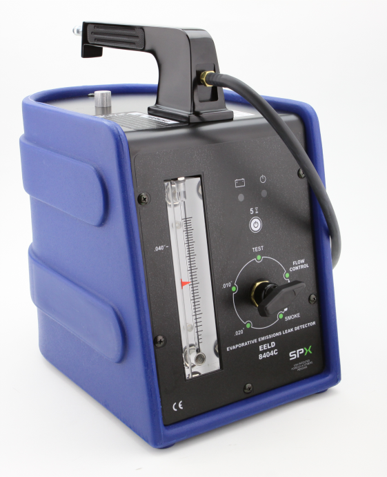
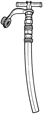
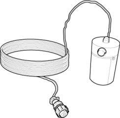
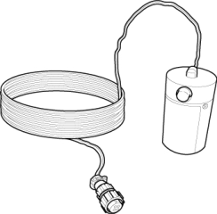
| 1. | To continue testing you will need Evaporative Emission Leak Detector (EELD) Kit, EELD And Accessory 8404C . |
| 2. | Connect the red power lead of the EELD to the battery positive terminal and the black ground lead to battery negative terminal. |
| 3. | Disconnect the vacuum hoses at the Evap Purge Solenoid. |
| 4. | Connect the SMOKE supply tip (black hose) to the “CAN” port on the Evap Purge Solenoid. |
| 5. | Set the smoke/air control switch to SMOKE. |
| 6. | While still holding the remote smoke/air start button, check to see if smoke is exiting the purge valve. This indicates that there is a leak internal to the purge valve. |
| NOTE: | This is an optional method of checking the purge valve for leaks if the EELD is unavailable. |
| 7. | Disconnect the Smoke supply tip from the vacuum supply hoses at the Evap Purge Solenoid. |
| 8. | Using a hand vacuum pump, apply 10 in Hg to the "CAN" side of the Evap Purge Solenoid. |
| 9. | Observe the vacuum gauge for at least 15 seconds. |
| NOTE: | The solenoid should hold vacuum for a minimum of 15 seconds. |
Is smoke visible from the Evaporative Purge Solenoid or NOT hold a vacuum?
Yes
- Replace the Evap Purge Solenoid. (Refer to 25 - Emissions Control/Evaporative Emissions/SOLENOID, Evaporative Emissions Purge - Removal) .
- Perform the POWERTRAIN VERIFICATION TEST. (Refer to 28 - DTC-Based Diagnostics/MODULE, Powertrain Control (PCM) - Standard Procedure).
No
- Go To 6
| 1. | Turn the ignition off. |
| 2. | Connect the previously disconnected vacuum hose. |
| 3. | Disconnect the ESIM Switch harness connector. |
| 4. | Ignition on, engine not running. |
| 5. | Monitor the ESIM Switch state on the scan tool. |
| 6. | Carefully connect a jumper wire between the ESIM Signal circuit and the Ground circuit in the ESIM Switch harness connector. |
| 7. | Monitor the ESIM Switch state on the scan tool. |
Did the Switch change from OPEN to CLOSED when the jumper wire was installed?
Yes
- Go To 9
No
-
Go To 7
NOTE: Remove the jumper wire before continuing.
7. EXCESSIVE RESISTANCE IN THE ESIM SIGNAL CIRCUIT
| 1. | Turn the ignition off. |
| 2. | Disconnect the PCM C1 harness connector. |
| 3. | Measure the resistance of the ESIM Signal circuit from the ESIM harness connector to the appropriate terminal of the PCM C1 harness connector. |
Is the resistance below 5.0 Ohms?
Yes
- Go To 8
No
- Repair the open or excessive resistance in the ESIM Signal circuit.
- Perform the POWERTRAIN VERIFICATION TEST. (Refer to 28 - DTC-Based Diagnostics/MODULE, Powertrain Control (PCM) - Standard Procedure).
8. EXCESSIVE RESISTANCE IN THE GROUND CIRCUIT
| 1. | Using a 12-volt test light connected to B+, probe the Ground circuit in the ESIM harness connector. |
| NOTE: | The test light should illuminate brightly. Compare the brightness to that of a direct connection to B- (ground). |
Does the test light illuminate brightly?
Yes
- Go To 14
No
- Repair the excessive resistance in the Ground circuit.
- Perform the POWERTRAIN VERIFICATION TEST. (Refer to 28 - DTC-Based Diagnostics/MODULE, Powertrain Control (PCM) - Standard Procedure).
9. VERIFY EVAPORATIVE EMISSION LEAK
Keep lit cigarettes, sparks, flames,
and other ignition sources away from the test area to prevent the
ignition of explosive gases. Keep the test area well ventilated. Failure
to do so may result in possible serious or fatal injury.
WARNING:
| 1. | Turn the ignition off. |
| 2. | To continue testing you will need Evaporative Emission Leak Detector (EELD) Kit, EELD And Accessory 8404C . |
| NOTE: | The fuel tank should have between 20% and 80% of fuel tank capacity to properly test the Evaporative system. |
| 3. | Connect the red power lead of EELD to the battery positive terminal and the black ground lead to battery negative terminal. |
| 4. | Block the vent hose of the Evaporative Canister. |
| 5. | Connect shop air to the EELD. |
| 6. | Set the smoke/air control switch to AIR. |
| 7. | Insert the tester's AIR supply tip (clear hose) into the .040 orifice on the tester's control panel. |
| 8. | Press the remote smoke/air start button. |
| 9. | Position the red flag on the air flow meter so it is aligned with the indicator ball. |
| 10. | When the calibration is complete, release the remote button. The EELD flow meter is now calibrated in liters per minute. |
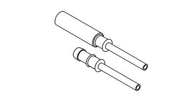
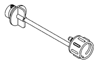
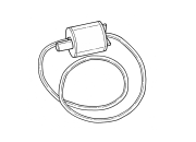
| 11. | Install the Adapter, Evaporative Service Port 8404-14 on the vehicle's service port (if equipped) or install the Smoke Machine Adapters 8404-ADP into the filter line. |
| 12. | Connect the Air supply hose from the EELD to the service port (if equipped) or to the Smoke Machine Adapters 8404-ADP . |
| 13. | Press the remote button to activate AIR flow. |
| 14. | Compare the flow meter indicator ball reading to the red flag. |
| 15. | ABOVE the red flag indicates a leak present. |
| 16. | BELOW the red flag indicates a sealed system. |
Is the indicator ball above the red flag?
Yes
- Go To 10
No
- Go To 12
10. EVAPORATIVE EMISSION LEAK DETECTION
| NOTE: | A thorough visual inspection of the Evaporative system hoses, tubes and connections may save time in your diagnosis. Look for any physical damage or signs of wetness at connections. The strong smell of fuel vapors may aid diagnosis also. |
| 1. | Remove the Air supply hose from the service port or the Smoke Machine Adapters 8404-ADP . |
| 2. | Connect the SMOKE supply tip (black hose) to the service port (if equipped) or to the Smoke Machine Adapters 8404-ADP . |
| 3. | Set the smoke/air control switch to SMOKE. |
| NOTE: | The flow meter indicator ball will not move at this point. |
| 4. | Press the remote smoke/air start button. |
| NOTE: | Make sure that smoke has filled the Evaporative system by continuing to press the remote smoke/air start button, remove the vehicle fuel cap and wait for the smoke to exit. Once smoke is indicated reinstall the fuel cap. |
| NOTE: | For optimal performance, introduce smoke into the system for an additional 60 seconds; continue introducing smoke at 15 second intervals, as necessary. |
| 5. | While still holding the remote smoke/air start button, use the Light, White 8404-CLL to follow the Evaporative system path and look for the source of the leak indicated by exiting smoke. |
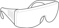
| 6. | If a leak is concealed from view (i.e., top of fuel tank), release the remote smoke/air start button and use the Light, UV 8404-UVL and the Goggles, Yellow 8404-20 to look for residual traces of dye that are left behind by the smoke. |
| 7. | The exiting smoke deposits a residual fluid that is either bright green or bright yellow in color when viewed with a UV light. |
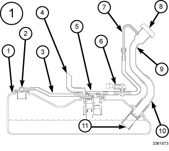
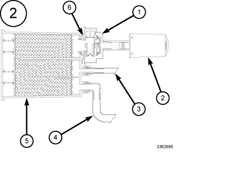
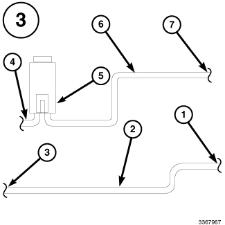
| NOTE: | The Evaporative System is divided into three zones. A leak from any of these zones can cause this DTC to set. The lists below specify the possible leak points in that specific zone. For further assistance see the Zone Identification Charts below. |
 |
|
ZONE 1 EVAP SYSTEM COMPONENTS |
|
|---|---|
|
CALLOUT |
DESCRIPTION |
| 1 | Fuel Tank |
| 2 | Fuel Tank Vent (Check Valve) |
| 3 | Vapor Line to Canister |
| 4 | Fuel Tank to Canister Vapor Line |
| 5 | Control Valve |
| 6 | Fuel tank Pressure Sensor |
| 7 | Vapor Recirculation Line |
| 8 | Fuel Cap |
| 9 | Fuel Fill Tube |
| 10 | Fuel Fill Tube to Tank connector |
| 11 | Fuel Fill Check Valve |
 |
|
ZONE 2 EVAP SYSTEM COMPONENTS |
|
|---|---|
|
CALLOUT |
DESCRIPTION |
| 1 | ESIM switch |
| 2 | Filter |
| 3 | Evaporative Purge connection |
| 4 | Fuel Tank to Canister Vapor Line |
| 5 | Evaporative Canister |
| 6 | ESIM Switch O-Ring Seal |
 |
|
ZONE 3 EVAP SYSTEM COMPONENTS |
|
|---|---|
|
CALLOUT |
DESCRIPTION |
| 1 | Connection to Canister |
| 2 | Chassis Purge Line |
| 3 | Connection to Evaporative Purge Harness |
| 4 | Chassis Evaporative Purge to Engine Vacuum line and connection |
| 5 | Evaporative Purge Valve |
| 6 | Evaporative Purge Vacuum Line |
| 7 | Connection to Chassis Line |
| NOTE: | Carefully inspect the vent side of the Evaporative Canister. Due to the filtering system in the canister the smoke or dye may or may not be visible. Introducing smoke into the filtered side of the canister may assist in locating the leak. |
Select the appropriate response from the list below:
A leak was found at the gas cap or fuel filler tube.
- Go To 11
A leak was found in one or more of the Evaporative System zones.
- If the leak is at a hose connection, remove the hose then reconnect the hose and check for a leak again. All other leaks, repair as necessary.
- Perform the POWERTRAIN VERIFICATION TEST. (Refer to 28 - DTC-Based Diagnostics/MODULE, Powertrain Control (PCM) - Standard Procedure).
No leaks were detected.
- Go To 12
| 1. | Remove the SMOKE supply tip (black hose) from the service port (if equipped) or to the Smoke Machine Adapters 8404-ADP . |
| 2. | Install the Adapter, Leak Check 8382 (1/4 turn cap) or Adapter, Fuel Tank 6922 (screw on cap) and Adapter, Leak Check 8399 (secondary seal depressor) and repeat step 10. |
| NOTE: | The gas cap adapter is being used as a known good cap. |
Was a leak found at the gas cap adapter?
Yes
- Replace the Fuel Filler tube assembly. .
- Perform the POWERTRAIN VERIFICATION TEST. (Refer to 28 - DTC-Based Diagnostics/MODULE, Powertrain Control (PCM) - Standard Procedure).
No
- Replace the gas cap.
- Perform the POWERTRAIN VERIFICATION TEST. (Refer to 28 - DTC-Based Diagnostics/MODULE, Powertrain Control (PCM) - Standard Procedure).
12. EVAPORATIVE PURGE HOSE/TUBE AND FRESH AIR FILTER OBSTRUCTION
| 1. | Inspect the Evaporative Purge hose/tube for proper routing and installation between the Evap Purge Solenoid and the Fuel Tank between the Fuel Tank and the Evap Purge Canister |
| 2. | Make sure the hose/tube and fresh air filter are not damaged, kinked and free from any obstructions. |
Were any problems found?
Yes
- Repair or replace as necessary.
- Perform the POWERTRAIN VERIFICATION TEST. (Refer to 28 - DTC-Based Diagnostics/MODULE, Powertrain Control (PCM) - Standard Procedure).
No
- Go To 13
13. EVAPORATIVE SYSTEM INTEGRITY MONITOR SWITCH
Were any problems found?
Yes
- Repair and Replace as necessary.
- Perform the POWERTRAIN VERIFICATION TEST. (Refer to 28 - DTC-Based Diagnostics/MODULE, Powertrain Control (PCM) - Standard Procedure).
No
- Replace the ESIM Switch in accordance with the Service Information.
- Perform the POWERTRAIN VERIFICATION TEST. (Refer to 28 - DTC-Based Diagnostics/MODULE, Powertrain Control (PCM) - Standard Procedure).
14. POWERTRAIN CONTROL MODULE (PCM)
| 1. | Using the wiring diagram/schematic as a guide, inspect the wiring and connectors between the Evap Purge Solenoid Assembly, Evaporative System Integrity Monitor (ESIM) Switch and the Powertrain Control Module (PCM). |
| 2. | Look for any chafed, pierced, pinched or partially broken wires. |
| 3. | Look for broken, bent, pushed out or corroded terminals. |
| 4. | Monitor the scan tool data relative to these circuits and wiggle test the wiring and connectors. |
| 5. | Look for the data to change or for the DTC to reset during the wiggle test. |
| 6. | Perform any Technical Service Bulletins that may apply. |
Were there any problems found?
Yes
- Repair as necessary.
- Perform the POWERTRAIN VERIFICATION TEST. (Refer to 28 - DTC-Based Diagnostics/MODULE, Powertrain Control (PCM) - Standard Procedure).
No
- Replace and program the Powertrain Control Module in accordance with the service information. (Refer to 08 - Electrical/8E - Electronic Control Modules/MODULE, Powertrain Control - Removal) .
- Perform the POWERTRAIN VERIFICATION TEST. (Refer to 28 - DTC-Based Diagnostics/MODULE, Powertrain Control (PCM) - Standard Procedure).