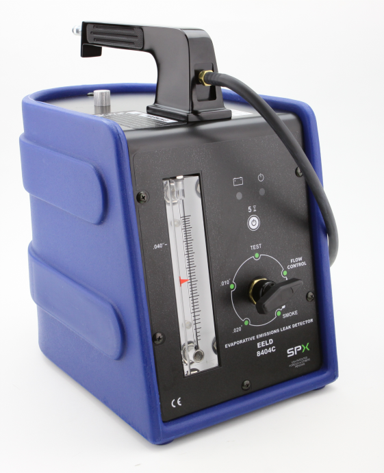
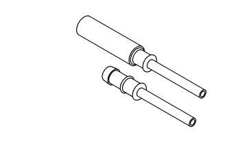
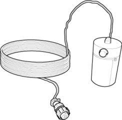
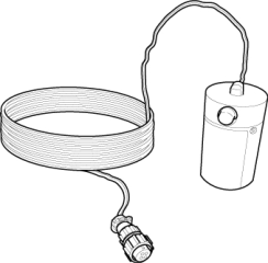
For a complete wiring diagram, refer to the Wiring
Information.
Theory of Operation
The Evap Purge Monitor tests the integrity of the hoses/tube between
the throttle body/intake and the fuel tank. The monitor is a two stage
test and runs only after the Evap system passes the small leak test.
Stage one is non-intrusive. The Powertrain Control Module (PCM) monitors
the purge vapor ratio and the Evaporative System Integrity Monitor
(ESIM) Switch closed ratio. If the purge vapor ratio is above a calculated
value, the monitor passes. If the ESIM switch closed ratio is greater
than calculated value when purge flow is greater than a minimum value,
the monitor passes. Stage two is an intrusive test and runs only if
stage one does not pass. The PCM commands the purge solenoid to flow
at a specified rate to force the purge vapor ratio to update. The
ratio is compared to a calibrated specification. If it is less than
specified, a one trip failure is recorded. This test can detect if
the purge hose is off, obstructed, or the purge valve is not operational.
When Monitored:
With the
engine running, during a cold start test with the fuel level above
12%, ambient temperature between 4°C and 32°C (39°F and 89°F) and
the fuel system in closed loop. The test runs when the small leak
test is maturing.
Set Condition:
The PCM activates
the Evap Purge Solenoid to pull the Evap system into a vacuum to close
the ESIM Switch. Once the ESIM Switch is closed, the PCM turns the
Evap Purge solenoid off to seal the Evap system. If the ESIM Switch
reopens before the calibrated amount of time, a large leak error is
detected. Two Trip Fault. Three good trips to turn off the MIL.
Possible Causes
EVAP PURGE SOLENOID
VACUUM SUPPLY
EVAP PURGE
HOSE/TUBE OBSTRUCTION
EVAP SYSTEM
LEAK
EVAPORATIVE SYSTEM
INTEGRITY MONITOR (ESIM) SWITCH
1.
VEHICLE HISTORY
AND SERVICE BULLETIN INVESTIGATION
1.
Ignition on, engine
not running.
2.
Using the scan
tool, read DTCs. Record the related Freeze Frame data if any DTCs
are present.
3.
Check the following
items which may assist in repairing the customer's complaint successfully:
Check the vehicle's
repair history. If the vehicle has a repair history that pertains
to the customer's current complaint, review the repair.
Inspect the vehicle
for any aftermarket accessories that may have been installed incorrectly.
Check for any service
bulletin(s) related to the customer's complaint or DTCs. If a service
bulletin applies, follow the instructions of the service bulletin.
Choose
the following scenario that best applies:
The vehicle
inspection or service bulletin repaired the customer's complaint.
Testing complete.
A DTC
is present, the vehicle inspection revealed no concerns, no service
bulletins apply, or the service bulletin did not repair the customer's
complaint.
Test complete, the
condition or conditions that originally set this DTC are not present
at this time. Using the wiring diagrams as a guide, check all related
splices and connectors for signs of water intrusion, corrosion, pushed
out or bent terminals, and correct pin tension.
Keep lit cigarettes, sparks, flames,
and other ignition sources away from the test area to prevent the
ignition of explosive gases. Keep the test area well ventilated. Failure
to do so may result in possible serious or fatal injury.
The fuel tank should
have between 20% and 80% of fuel tank capacity to properly test the
Evap system.
2.
Connect the red
power lead of the EELD to the battery positive terminal and the black
ground lead to battery negative terminal.
3.
Connect shop air
to the EELD.
4.
Set the smoke/air
control switch to AIR.
5.
Insert the tester's
AIR supply tip (clear hose) into the appropriate calibration orifice
on the tester's control panel (based on DTC leak size).
6.
Press the remote
smoke/air start button.
7.
Position the red
flag on the air flow meter so it is aligned with the indicator ball.
8.
When the calibration
is complete, release the remote button. The EELD flow meter is now
calibrated in liters per minute to the size leak indicated by the
DTC set in the PCM.
9.
Remove the Vent
Filter and install the service adapter
8404-ADP
into the vent
line.
10.
Connect the AIR
supply hose from the EELD to the adapter.
11.
Press the remote
button to activate AIR flow.
NOTE:
Larger volume fuel
tanks, lower fuel levels, or vehicles equipped with a Flow Management
Valve may indicate high flow and will require four to five minutes
to fill.
12.
Compare the flow
meter indicator ball reading to the red flag.
Review the Freeze Frame
data recorded in step 1. If the data indicates that the vehicle was
in motion when the DTC was set, verify that all hoses are properly
connected.
A thorough visual inspection
of the Evap system hoses, tubes, and connections may save time in
your diagnosis. Look for any physical damage or signs of wetness at
connections. The strong smell of fuel vapors may aid diagnosis also.
1.
Remove the Air
supply hose from the adapter.
2.
Connect the SMOKE
supply tip (black hose) to the adapter.
3.
Set the smoke/air
control switch to SMOKE.
NOTE:
The flow meter indicator
ball will not move in the smoke mode.
4.
Press the remote
smoke/air start button.
NOTE:
Make sure that smoke
has filled the Evap System by continuing to press the remote smoke/air
start button, remove the vehicle fuel cap (if applicable) or open
the flap (capless), and wait for the smoke to exit. Once smoke is
indicated reinstall the fuel cap or close the flap.
NOTE:
For optimal performance,
introduce smoke into the system for an additional 60 seconds; continue
introducing smoke at 15 second intervals, as necessary.
5.
While still holding
the remote smoke/air start button, use the white light
8404-CLL
to follow the
Evap system path, and look for the source of the leak indicated by
exiting smoke.
6.
If a leak is concealed
from view (i.e., top of fuel tank), release the remote smoke/air start
button, and use the ultraviolet (UV) black light
8404-UVL
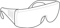
and the yellow
goggles
8404-20
to look for residual
traces of dye that is left behind by the smoke.
7.
The exiting smoke
deposits a residual fluid that is either bright green or bright yellow
in color when viewed with a UV light.
NOTE:
The Evap System is
divided into three zones. A leak from any of these zones can cause
this DTC to set. The lists below specify the possible leak points
in that specific zone. For further assistance see the Zone Identification
Charts below.
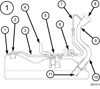
ZONE 1 EVAP SYSTEM
COMPONENTS
CALLOUT
DESCRIPTION
1
Fuel Tank
2
Fuel Tank
Vent (Check Valve)
3
Vapor Line
to Canister
4
Fuel Tank
to Canister Vapor Line
5
Control
Valve
6
Fuel tank
Pressure Sensor
7
Vapor Recirculation
Line
8
Fuel Cap
(if applicable)
9
Fuel Fill
Tube (System may be equipped with either a Fuel Cap or the Capless
Fuel Filler system, depending on the vehicles application)
10
Fuel Fill
Tube to Tank connector
11
Fuel Fill
Check Valve
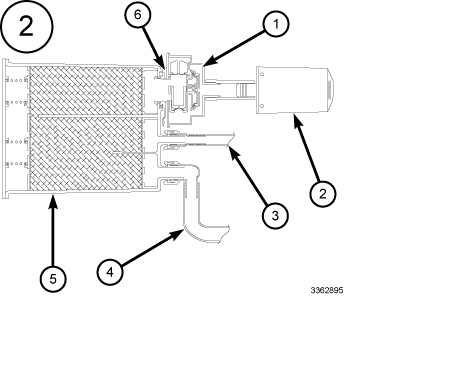
ZONE 2 EVAP SYSTEM
COMPONENTS
CALLOUT
DESCRIPTION
1
ESIM switch
2
Filter
3
Evaporative
Purge connection
4
Fuel Tank
to Canister Vapor Line
5
Evaporative
Canister
6
ESIM Switch
O-Ring Seal
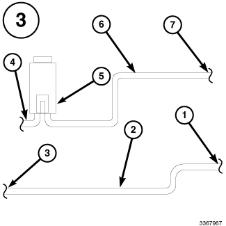
ZONE 3 EVAP SYSTEM COMPONENTS
CALLOUT
DESCRIPTION
1
Connection
to Canister
2
Chassis
Purge Line
3
Connection
to Evaporative Purge Harness
4
Chassis
Evaporative Purge to Engine Vacuum line and connection
5
Evaporative
Purge Valve
6
Evaporative
Purge Vacuum Line
7
Connection
to Chassis Line
NOTE:
Carefully inspect the
vent side of the Evap Canister. Due to the filtering system in the
canister the smoke may not be as thick. Introducing smoke into the
filtered side of the canister may assist in locating the leak.
Select
the appropriate response from the list below:
A leak
was found at the Fuel Cap (if applicable) or Fuel Filler Tube Assembly
Perform the appropriate
repair by replacing the Fuel Filler Tube Assembly and/or the Fuel
Cap (if applicable).
Verify that there is
good pin to terminal contact in the ESIM Switch and PCM harness connectors.
Replace the ESIM Switch in accordance with the service information
if no problems were found in the connectors.