P0593-SPEED CONTROL SWITCH 2 CIRCUIT HIGH
For a complete wiring diagram, refer to the Wiring Information.
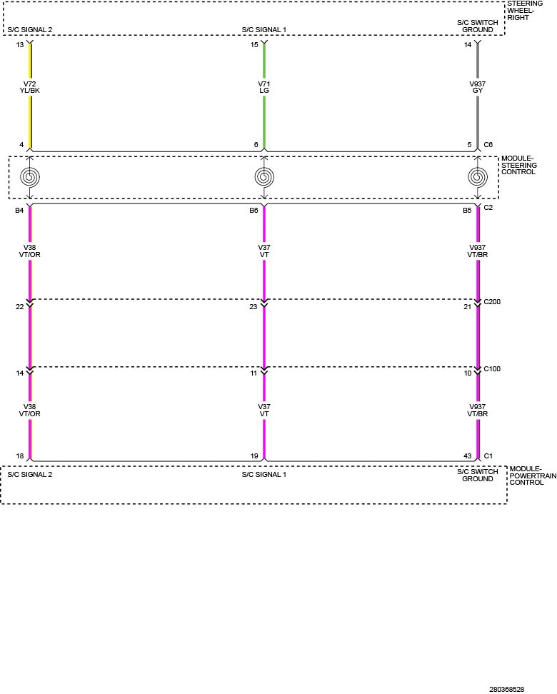 |
Theory of Operation
The Speed Control Switches are located in the Right Steering Wheel Switch. The Right Steering Wheel Switch is hardwired to the Powertrain Control Module (PCM) via the clockspring pass-through within the Steering Column Control Module (SCCM). The SCCM is located near the top of the steering column below the steering wheel. The SCCM includes the steering column shroud, the Steering Angle Sensor (SAS), the Clockspring, the Multi-function Switch, a Steering Column Power Tilt and Telescope Switch (if equipped), and a trim cover.
-
When Monitored:
Continuously with the ignition on.
-
Set Condition:
Fault signifies when the switch voltage is shorted high.
Possible Causes |
|---|
| S/C SIGNAL 2 CIRCUIT |
| SPEED CONTROL SWITCH (RIGHT STEERING WHEEL SWITCH) |
| CLOCKSPRING |
Always perform the Pre-Diagnostic Troubleshooting procedure before proceeding (Refer to 28 - DTC-Based Diagnostics/MODULE, Powertrain Control (PCM) - Standard Procedure).
Turn the ignition off disconnect
the 12-volt battery and wait two minutes before proceeding. Failure
to follow these instructions may result in possible serious or fatal
injury.
WARNING:
Do not place an intact non-deployed
airbag face down on a hard surface, the airbag propels into the air
if accidentally deployed. Failure to follow these instructions may
result in possible serious or fatal injury.
WARNING:
| 1. | Turn the ignition on, engine not running. |
| 2. | With the scan tool, read DTCs |
Does the scan tool display this DTC as active?
Yes
- Go To 2.
No
- Perform the INTERMITTENT CONDITION diagnostic procedure (Refer to 28 - DTC-Based Diagnostics/MODULE, Powertrain Control (PCM) - Standard Procedure).
2. CHECK THE (V72/V38) S/C SIGNAL 2 CIRCUIT FOR A SHORT TO VOLTAGE
| 1. | Turn the ignition off. |
| 2. | Remove the Driver Air Bag in accordance with the Service Information (Refer to 10 - Restraints/AIR BAG, Driver/Removal) . |
| 3. | Disconnect the Right Steering Wheel Switch harness connector. |
| 4. | Turn the ignition on, engine not running. |
| 5. | Measure the voltage of the (V72/V38) S/C Signal 2 circuit at the Right Steering Wheel Switch harness connector. |
Is the voltage above 5.2 volts?
Yes
- Repair the short to voltage in the (V72/V38) S/C Signal 2 circuit.
- Perform the PCM VERIFICATION TEST (Refer to 28 - DTC-Based Diagnostics/MODULE, Powertrain Control (PCM) - Standard Procedure).
No
- Go To 3.
3. RIGHT STEERING WHEEL SWITCH
| 1. | Connect a jumper between the (V72V38) S/C Signal 2 circuit and the (V937) S/C Switch Ground circuit at the Right Steering Wheel Switch harness connector. |
| 2. | With the scan tool, select View DTCs. |
Does the P0592-SPEED CONTROL SWITCH 2 CIRCUIT LOW set as active or pending with the jumper in place?
Yes
- Replace the Right Steering Wheel Switch in accordance with the Service Information (Refer to 08 - Electrical/8P - Speed Control/SWITCH, Speed Control/Removal) .
- Perform the PCM VERIFICATION TEST (Refer to 28 - DTC-Based Diagnostics/MODULE, Powertrain Control (PCM) - Standard Procedure).
No
- Go To 4.
4. STEERING WHEEL JUMPER HARNESS
| 1. | Turn the ignition off. |
| 2. | Disconnect the SCM C6 harness connector. |
| 3. | Connect a jumper between the (V72V38) S/C Signal 2 circuit and the (V937) S/C Switch Ground circuit at the SCM C6 component side. |
| 4. | Turn the ignition on, engine not running. |
| 5. | With the scan tool, select View DTCs. |
Does the P0592-SPEED CONTROL SWITCH 2 CIRCUIT LOW set as active or pending with the jumper in place?
Yes
- Replace the Steering Wheel Jumper Harness in accordance with the service information.
- Perform the PCM VERIFICATION TEST (Refer to 28 - DTC-Based Diagnostics/MODULE, Powertrain Control (PCM) - Standard Procedure).
No
- Go To 5.
| 1. | Turn the ignition off. |
| 2. | Disconnect the SCM C2 harness connector. |
| 3. | Connect a jumper between the (V72V38) S/C Signal 2 circuit and the (V937) S/C Switch Ground circuit at the SCM C2 harness connector. |
| 4. | Turn the ignition on, engine not running. |
| 5. | With the scan tool, select View DTCs. |
Does the P05892-SPEED CONTROL SWITCH 2 CIRCUIT LOW set as active or pending with the jumper in place?
Yes
- Replace the Clockspring in accordance with the Service Information (Refer to 10 - Restraints/CLOCKSPRING/Removal) .
- Perform the PCM VERIFICATION TEST (Refer to 28 - DTC-Based Diagnostics/MODULE, Powertrain Control (PCM) - Standard Procedure).
No
- Go To 6.
6. CHECK THE (V72V38) S/C SIGNAL 2 CIRCUIT FOR AN OPEN/HIGH RESISTANCE
| 1. | Turn the ignition off. |
| 2. | Disconnect the PCM C1 harness connector. |
| 3. | Measure the resistance of the (V72/V38) S/C Signal 2 circuit between the SCM C2 harness connector and the PCM C1 harness connector. |
Is the resistance below 5.0 Ohms?
Yes
- Go To 7.
No
- Repair the (V72/V38) S/C Signal 2 circuit for an open or high resistance.
-
Perform the PCM VERIFICATION
TEST (Refer to 28 - DTC-Based
Diagnostics/MODULE, Powertrain Control (PCM)
- Standard Procedure).
7. CHECK THE (V937) S/C SWITCH GROUND CIRCUIT FOR AN OPEN/HIGH RESISTANCE
| 1. | Measure the resistance of the (V937) S/C Switch Ground circuit between the SCM C2 harness connector and the PCM C1 harness connector. |
Is the resistance below 5.0 Ohms?
Yes
- Go To 8.
No
- Repair the (V937) S/C Switch Ground circuit for an open or high resistance.
-
Perform the PCM VERIFICATION
TEST (Refer to 28 - DTC-Based
Diagnostics/MODULE, Powertrain Control (PCM)
- Standard Procedure).
| 1. | Using the wiring diagram/schematic as a guide, inspect the wiring and connectors between the Right Steering Wheel Switch and the Powertrain Control Module. |
| 2. | Look for any chafed, pierced, pinched, or partially broken wires. |
| 3. | Look for broken, bent, pushed out or corroded terminals. |
| 4. | Perform any Technical Service Bulletins that may apply. |
Were any problems found?
Yes
- Repair as necessary.
- Perform the PCM VERIFICATION TEST (Refer to 28 - DTC-Based Diagnostics/MODULE, Powertrain Control (PCM) - Standard Procedure).
No
- Replace the Powertrain Control Module in accordance with the Service Information (Refer to 08 - Electrical/8E - Electronic Control Modules/MODULE, Powertrain Control/Removal) .
- Perform the PCM VERIFICATION TEST (Refer to 28 - DTC-Based Diagnostics/MODULE, Powertrain Control (PCM) - Standard Procedure).