P0685-AUTO SHUTDOWN RELAY CONTROL CIRCUIT
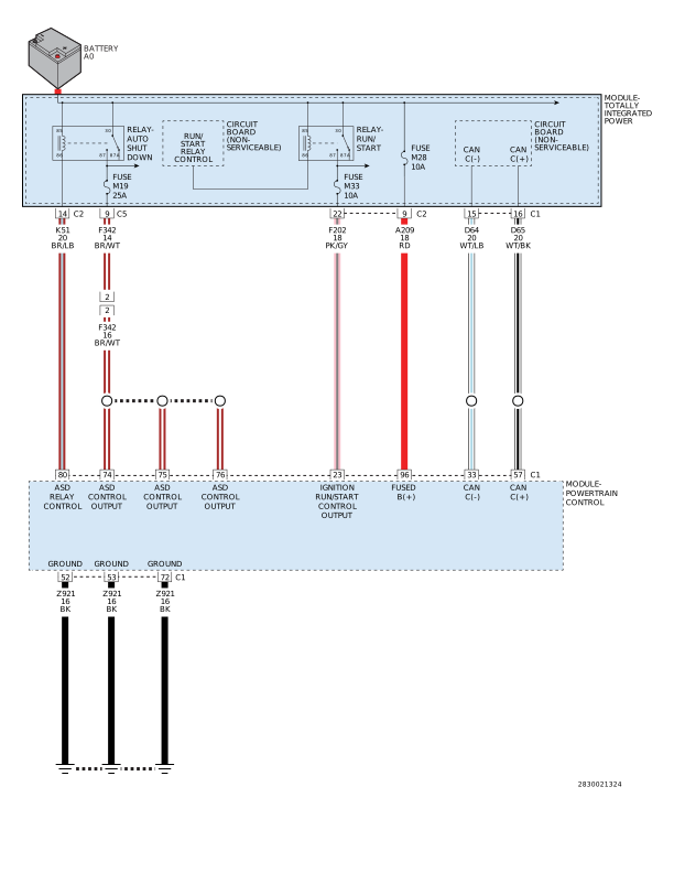
For a complete wiring diagram, refer to the Wiring Information.
 |
-
When Monitored:
When the ignition is turned off, during after-run mode of operation.
-
Set Condition:
The Powertrain Control Module (PCM) determines that the ASD Relay has shut off before the AFTER-RUN mode of operation has been completed.
POSSIBLE CAUSES |
|---|
| (K51) ASD RELAY CONTROL CIRCUIT OPEN |
| (K51) ASD RELAY CONTROL CIRCUIT SHORTED TO VOLTAGE |
| (K51) ASD RELAY CONTROL CIRCUIT SHORTED TO GROUND |
| LOSS OF POWERTRAIN CONTROL MODULE POWERS OR GROUNDS |
| ASD RELAY |
| POWERTRAIN CONTROL MODULE (PCM) |
Always perform the Pre-Diagnostic Troubleshooting procedure before proceeding. (Refer to 28 - DTC-Based Diagnostics/MODULE, Powertrain Control (PCM) - Standard Procedure).
| 1. | Turn the ignition on. |
| 2. | With the scan tool, check for additional DTCs. |
Are other DTCs present?
Yes
- Perform the diagnostics for the other DTCs before continuing.
- Perform the POWERTRAIN VERIFICATION TEST. (Refer to 28 - DTC-Based Diagnostics/MODULE, Powertrain Control (PCM) - Standard Procedure).
No
- Go To 2
2. CLEAR CODE AND CHECK IF THE DTC RESETS
| 1. | With the scan tool, erase PCM DTCs. |
| 2. | Perform several ignition key cycles, pausing for at least 10 seconds between each cycle. |
| 3. | Turn the ignition on. |
| 4. | With the scan tool, read PCM DTCs. |
Did this DTC Return?
Yes
- Go To 3
No
- Perform the INTERMITTENT CONDITION diagnostic procedure. (Refer to 28 - DTC-Based Diagnostics/MODULE, Powertrain Control (PCM) - Standard Procedure).
| 1. | Turn the ignition off. |
| 2. | Install a known good relay in place of the ASD Relay. |
| 3. | Turn the ignition on. |
| 4. | With the scan tool, erase PCM DTCs. |
| 5. | Perform several ignition key cycles, pausing for at least 10.0 seconds between each cycle. |
| 6. | Turn the ignition on. |
| 7. | With the scan tool, read PCM DTCs. |
Did this DTC return?
Yes
- Go To 4
No
- Replace the ASD Relay in accordance with the service information.
- Perform the POWERTRAIN VERIFICATION TEST. (Refer to 28 - DTC-Based Diagnostics/MODULE, Powertrain Control (PCM) - Standard Procedure).
4. CHECK PCM POWER AND GROUNDS
| 1. | Using the wiring information, check the PCM battery, ignition feed and ground circuits. |
Were any problem found with the PCM powers and grounds?
Yes
- Repair as necessary.
- Perform the POWERTRAIN VERIFICATION TEST. (Refer to 28 - DTC-Based Diagnostics/MODULE, Powertrain Control (PCM) - Standard Procedure).
No
- Go To 5
5. CHECK THE (K51) ASD RELAY CONTROL CIRCUIT FOR A SHORT TO VOLTAGE
| 1. | Turn the ignition off. |
| 2. | Remove the ASD Relay. |
| 3. | Disconnect the PCM C1 harness connector. |
| 4. | Turn the ignition on. |
| 5. | Measure the voltage on the (K51) ASD Relay Control circuit at terminal 86 of the ASD Relay connector. |
Is there any voltage present?
Yes
- Repair the (K51) ASD Relay Control circuit for a short to voltage.
- Perform the POWERTRAIN VERIFICATION TEST. (Refer to 28 - DTC-Based Diagnostics/MODULE, Powertrain Control (PCM) - Standard Procedure).
No
- Go To 6
6. CHECK THE (K51) ASD RELAY CONTROL CIRCUIT FOR A SHORT TO GROUND
| 1. | Turn the ignition off. |
| 2. | Measure the resistance between ground and the (K51) ASD Relay Control circuit at terminal 86 of the ASD Relay connector. |
Is the resistance above 10k Ohms?
Yes
- Go To 7
No
- Repair the (K51) ASD Relay Control circuit for a short to ground.
- Perform the POWERTRAIN VERIFICATION TEST. (Refer to 28 - DTC-Based Diagnostics/MODULE, Powertrain Control (PCM) - Standard Procedure).
7. CHECK THE (K51) ASD RELAY CONTROL CIRCUIT FOR AN OPEN/HIGH RESISTANCE
Do not probe the PCM harness connectors. Probing the PCM harness
connectors will damage the PCM terminals resulting in poor terminal
to pin connection. Install the GPEC Diagnostic Adaptor to perform
the diagnosis.
CAUTION:
| 1. | Connect the Adapter, GPEC Diagnostic 10436 . |
| 2. | Measure the resistance of the (K51) ASD Relay Control circuit between the ASD Relay connector and the GPEC Adapter. |
Is the resistance below 5.0 Ohms?
Yes
- Replace and program the Powertrain Control Module in accordance with the Service Information. (Refer to 08 - Electrical/8E - Electronic Control Modules/MODULE, Powertrain Control - Removal) .
- Perform the POWERTRAIN VERIFICATION TEST. (Refer to 28 - DTC-Based Diagnostics/MODULE, Powertrain Control (PCM) - Standard Procedure).
No
- Repair the (K51) ASD Relay Control circuit for an open or high resistance.
- Perform the POWERTRAIN VERIFICATION TEST. (Refer to 28 - DTC-Based Diagnostics/MODULE, Powertrain Control (PCM) - Standard Procedure).