P1573-BRAKE PEDAL STUCK OFF
For a complete wiring diagram, refer to the Wiring Information.
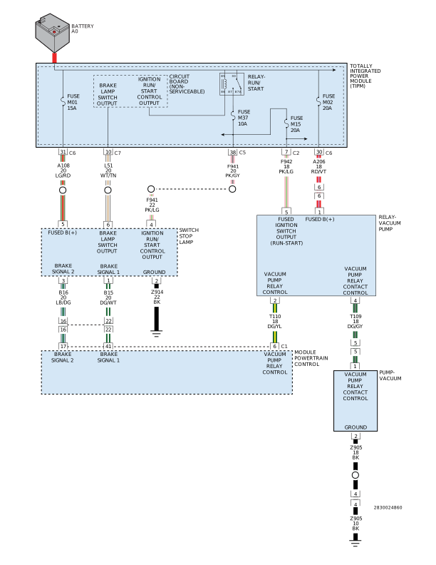 |
Theory of Operation
The Powertrain Control Module (PCM) monitors the vehicle braking via the Stop Lamp Switch. For accuracy, the PCM monitors two separate brake switch signals. The operating mode of these signals are as follows:
Brake Switch Signal 1 operation: The PCM sends out a 12 Volt, low amperage signal, which may not illuminate a test light, on the (B15) Brake Switch 1 circuit. The PCM monitors the voltage on this circuit to indicate if the brake pedal is depressed or released. When the brake pedal is released, the (B15) Brake Switch 1 circuit is connected to the (Z914) ground circuit and the PCM reads Zero Volts on the (B15) Brake Switch 1 circuit. When the pedal is pressed, the path to ground is broken and the PCM reads 12 Volts on the (B15) Brake Switch 1 circuit.
Brake Switch Signal 2 operation: 12 Volts are sent on the (F941) Ignition Switch Start/Run circuit through the Stop Lamp Switch to the PCM on the (B16) Brake Switch 2 circuit. The PCM monitors the voltage on this circuit to indicate if the brake pedal is depressed or released. Zero Volts on the (B16) Brake Switch 2 circuit indicates to the PCM that the pedal is pressed, and 12 Volts indicate that the brake pedal is released.
-
When Monitored:
Ignition on, In plant mode passed the Applied test.
-
Set Condition:
The Powertrain Control Module (PCM) recognizes the Brake Pedal could not electronically indicate the released (Off) position with both switches. If P1572 sets, P1573 will also set. One trip fault.
Possible Causes |
|---|
| (B16) BRAKE SWITCH 2 SIGNAL CIRCUIT SHORTED TO VOLTAGE |
| (B15) BRAKE SWITCH 1 SIGNAL CIRCUIT SHORTED TO GROUND |
| STOP LAMP SWITCH |
| POWERTRAIN CONTROL MODULE (PCM) |
Always perform the Pre-Diagnostic Troubleshooting procedure before proceeding. (Refer to 28 - DTC-Based Diagnostics/MODULE, Powertrain Control (PCM) - Standard Procedure).
Diagnostic Test
| NOTE: | Make sure the Stop Lamp Switch is adjusted properly before continuing. |
| 1. | Ignition on, engine not running. |
| 2. | With the scan tool, select View DTCs. |
Is the DTC Active at this time?
Yes
- Go To 2
No
- Perform the INTERMITTENT CONDITION diagnostic procedure. (Refer to 28 - DTC-Based Diagnostics/MODULE, Powertrain Control (PCM) - Standard Procedure).
| 1. | Turn the ignition off. |
| 2. | Disconnect the Stop Lamp Switch harness connectors. |
| 3. | Measure the resistance between the (Z908) Ground circuit terminal and the (B15) Brake Switch 1 Signal terminal in the Stop Lamp Switch. |
| 4. | Apply and release the brake pedal while monitoring the Ohmmeter. |
Does the resistance change from below 5.0 Ohms to an open circuit when pressing and releasing the brake switch?
Yes
- Go To 3
No
- Replace the Stop Lamp Switch.
- Perform the POWERTRAIN VERIFICATION TEST. (Refer to 28 - DTC-Based Diagnostics/MODULE, Powertrain Control (PCM) - Standard Procedure).
| 1. | Measure the resistance between the (A108) Fused Ignition Switch Output circuit terminal and the (B16) Brake Switch 2 Signal terminal in the Stop Lamp Switch. |
| 2. | Apply and release the brake pedal while monitoring the Ohmmeter. |
Does the resistance change from below 5.0 Ohms to an open circuit when pressing and releasing the Stop Lamp switch?
Yes
- Go To 4
No
- Verify that there is good pin to terminal contact in the Switch and Powertrain Control Module connectors. Replace the Stop Lamp Switch if no problems were found in the connectors.
- Perform the POWERTRAIN VERIFICATION TEST. (Refer to 28 - DTC-Based Diagnostics/MODULE, Powertrain Control (PCM) - Standard Procedure).
4. (B16) BRAKE SWITCH 2 SIGNAL CIRCUIT SHORTED TO VOLTAGE
| 1. | Disconnect the PCM C1 harness connector. |
| 2. | Ignition on, engine not running. |
| 3. | Measure the voltage on the (B16) Brake Switch 2 Signal circuit in the Stop Lamp Switch harness connector. |
Is there any voltage present?
Yes
- Repair the (B16) Brake Switch 2 Signal circuit. for a short to voltage
- Perform the POWERTRAIN VERIFICATION TEST. (Refer to 28 - DTC-Based Diagnostics/MODULE, Powertrain Control (PCM) - Standard Procedure).
No
- Go To 5
5. CHECK THE (B15) BRAKE SWITCH 1 SIGNAL CIRCUIT FOR A SHORT TO GROUND
| 1. | Turn the ignition off. |
| 2. | Measure the resistance between ground and the (B15) Brake Switch 1 Signal circuit in the Stop Lamp Switch harness connector. |
Is the resistance above 10k Ohms?
Yes
- Go To 6
No
- Repair the (B15) Brake Switch 1 Signal circuit for a short to ground.
- Perform the POWERTRAIN VERIFICATION TEST. (Refer to 28 - DTC-Based Diagnostics/MODULE, Powertrain Control (PCM) - Standard Procedure).
6. POWERTRAIN CONTROL MODULE (PCM)
| 1. | Using the wiring diagram/schematic as a guide, inspect the wiring and connectors between the Stop Lamp Switch and the Powertrain Control Module (PCM). |
| 2. | Look for any chafed, pierced, pinched or partially broken wires. |
| 3. | Look for broken, bent, pushed out or corroded terminals. Verify that there is good pin to terminal contact in the Switch and Powertrain Control Module connectors. |
| 4. | Perform any Technical Service Bulletins that may apply. |
Were there any problems found?
Yes
- Repair as necessary.
- Perform the POWERTRAIN VERIFICATION TEST. (Refer to 28 - DTC-Based Diagnostics/MODULE, Powertrain Control (PCM) - Standard Procedure).
No
- Replace and program the Powertrain Control Module in accordance with the Service Information.
- Perform the POWERTRAIN VERIFICATION TEST. (Refer to 28 - DTC-Based Diagnostics/MODULE, Powertrain Control (PCM) - Standard Procedure).