P2107-ELECTRONIC THROTTLE CONTROL MODULE PROCESSOR
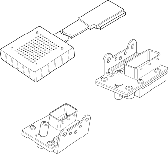
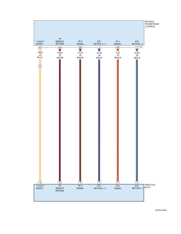
For a complete wiring diagram, refer to the Wiring Information.
 |
Thoery of operation
The Electronic Throttle Control (ETC) motor is controlled by the Powertrain Control Module (PCM). The DC motor located in the throttle body drives the throttle blade. In order to decrease idle speed, along with spark and fuel delivery changes the PCM commands the throttle closed reducing air flow into the engine and the idle speed decreases. In order to increase idle speed, the PCM commands the throttle plate open allowing more air to pass the throttle plate.
-
When Monitored:
With the ignition on and the ETC Motor is not in Limp Home mode.
-
Set Condition:
When the Powertrain Control Module (PCM) detects an internal error or a short between the ETC Motor - and ETC Motor + circuits in the ETC Motor Driver. One trip fault. ETC light is flashing.
Possible Causes |
|---|
| THROTTLE PLATE / BORE INSPECTION |
| (K124) ETC POSITIVE CIRCUIT SHORTED TO VOLTAGE |
| (K126) ETC NEGATIVE CIRCUIT SHORTED TO VOLTAGE |
| (K124) ETC POSITIVE CIRCUIT SHORTED TO THE (K126) ETC NEGATIVE CIRCUIT |
| (K124) ETC POSITIVE CIRCUIT OPEN |
| (K124) ETC POSITIVE CIRCUIT SHORTED TO GROUND |
| (K126) ETC NEGATIVE CIRCUIT OPEN |
| (K126) ETC NEGATIVE CIRCUIT SHORTED TO GROUND |
| LOW BATTERY VOLTAGE |
| ETC MOTOR/THROTTLE BODY |
| POWERTRAIN CONTROL MODULE (PCM) |
Always perform the Pre-Diagnostic Troubleshooting procedure before proceeding. (Refer to 28 - DTC-Based Diagnostics/MODULE, Powertrain Control (PCM) - Standard Procedure).
| NOTE: | Diagnose and repair P2100-ELECTRONIC THROTTLE CONTROL CIRCUIT if set with P2107-ELECTRONIC THROTTLE CONTROL MODULE PROCESSOR DTC before continuing. |
| 1. | Check for any related TSBs. |
| 2. | Verify the PCM is at the latest calibration (flash level). |
| NOTE: | An intermittent loss of power to the PCM without performing an ETC Relearn procedure may cause this DTC to set. |
| 3. | Flash the Powertrain Control Module in accordance with the Service Information if any updates are available. |
| 4. | Start the engine. |
| 5. | Allow the engine to reach normal operating temperature. |
| 6. | Operate the accelerator pedal. (do not exceed 3500 rpm) |
| 7. | Test drive the vehicle for 10 miles on a flat road surface. |
| NOTE: | Diagnose and repair DTC P2100-ELECTRONIC THROTTLE CONTROL CIRCUIT before continuing. |
Did DTC P2107-ELECTRONIC THROTTLE CONTROL MODULE PROCESSOR set active or pending at this time?
Yes
- Go To 2
No
- Perform the INTERMITTENT CONDITION diagnostic procedure. (Refer to 28 - DTC-Based Diagnostics/MODULE, Powertrain Control (PCM) - Standard Procedure).
| 1. | Turn the ignition off. |
| 2. | Remove the Air Cleaner Assembly from the Throttle Body. |
| 3. | Check for any signs of a foreign material (ice or dirt) on the Throttle Plate or in the bore causing the Throttle Plate to stick. |
Were any signs of foreign material or scoring of the throttle plate or bore found?
Yes
- Remove the debris if possible or replace the Throttle Body Assembly. (Refer to 14 - Fuel System/Fuel Injection/THROTTLE BODY - Removal) . Disconnect the Battery when replacing the Throttle Body Assembly. After installation is complete, use a scan tool and select the ETC RELEARN function.
- Perform the POWERTRAIN VERIFICATION TEST. (Refer to 28 - DTC-Based Diagnostics/MODULE, Powertrain Control (PCM) - Standard Procedure).
No
- Go To 3
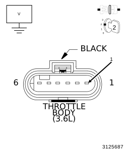
3. (K124) ETC POSITIVE CIRCUIT SHORTED TO VOLTAGE
 |
| 1. | Turn the ignition off. |
| 2. | Disconnect the Throttle Body harness connector. |
| 3. | Disconnect the PCM C2 harness connector. |
| 4. | Ignition on, engine not running. |
| 5. | Measure the voltage on the (K124) ETC Positive circuit at the Throttle Body harness connector. |
Is there any voltage present?
Yes
- Repair the short to voltage on the (K124) ETC Positive circuit.
- Perform the POWERTRAIN VERIFICATION TEST. (Refer to 28 - DTC-Based Diagnostics/MODULE, Powertrain Control (PCM) - Standard Procedure).
No
-
Go To 4
4. (K126) ETC NEGATIVE CIRCUIT SHORTED TO VOLTAGE
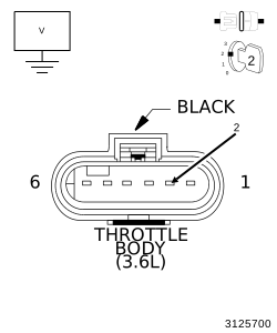 |
| 1. | Measure the voltage on the (K126) ETC Negative circuit at the Throttle Body harness connector. |
Is there any voltage present?
Yes
- Repair the short to voltage in the (K126) ETC Negative circuit.
- Perform the POWERTRAIN VERIFICATION TEST. (Refer to 28 - DTC-Based Diagnostics/MODULE, Powertrain Control (PCM) - Standard Procedure).
No
-
Go To 5
5. (K124) ETC POSITIVE CIRCUIT SHORTED TO THE (K126) ETC NEGATIVE CIRCUIT
| 1. | Turn the ignition off. |
| 2. | Measure the resistance between the (K124) ETC Positive circuit and the (K126) ETC Negative circuit at the Throttle Body harness connector. |
Is the resistance below 100 Ohms?
Yes
- Repair the short between the (K124) ETC Positive circuit and the (K126) ETC Negative circuit.
- Perform the POWERTRAIN VERIFICATION TEST. (Refer to 28 - DTC-Based Diagnostics/MODULE, Powertrain Control (PCM) - Standard Procedure).
No
-
Go To 6
6. (K124) ETC POSITIVE CIRCUIT OPEN
Do not probe the PCM harness connectors. Probing the PCM harness
connectors will damage the PCM terminals resulting in poor terminal
to pin connection. Install the GPEC Diagnostic Adaptor to perform
the diagnosis.
CAUTION:
| 1. | Connect the Adapter, GPEC Diagnostic 10436 . |
| 2. | Measure the resistance of the (K124) ETC Positive circuit from the Throttle Body harness connector to the GPEC Adaptor. |
Is the resistance below 5.0 Ohms?
Yes
- Go To 7
No
- Repair the open in the (K124) ETC Positive circuit.
-
Perform the POWERTRAIN
VERIFICATION TEST. (Refer to
28 - DTC-Based Diagnostics/MODULE, Powertrain Control (PCM)
- Standard
Procedure).
7. (K124) ETC POSITIVE CIRCUIT SHORTED TO GROUND
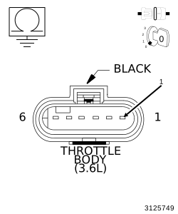 |
| 1. | Measure the resistance between ground and the (K124) ETC Positive circuit at the Throttle Body harness connector. |
Is the resistance below 100 Ohms?
Yes
- Repair the short to ground in the (K124) ETC Positive circuit.
- Perform the POWERTRAIN VERIFICATION TEST. (Refer to 28 - DTC-Based Diagnostics/MODULE, Powertrain Control (PCM) - Standard Procedure).
No
-
Go To 8
8. (K126) ETC NEGATIVE CIRCUIT OPEN
| 1. | Measure the resistance of the (K126) ETC Negative circuit from the Throttle Body harness connector to the GPEC Adaptor. |
Is the resistance below 5.0 Ohms?
Yes
- Go To 9
No
- Repair the open in the (K126) ETC Negative circuit.
-
Perform the POWERTRAIN
VERIFICATION TEST. (Refer to
28 - DTC-Based Diagnostics/MODULE, Powertrain Control (PCM)
- Standard
Procedure).
9. (K126) ETC NEGATIVE CIRCUIT SHORTED TO GROUND
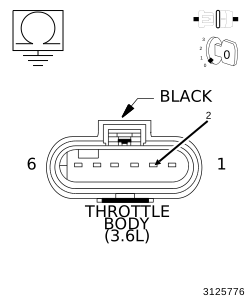 |
| 1. | Measure the resistance between ground and the (K126) ETC Negative circuit at the Throttle Body harness connector. |
Is the resistance below 100 Ohms?
Yes
- Repair the short to ground in the (K126) ETC Negative circuit.
- Perform the POWERTRAIN VERIFICATION TEST. (Refer to 28 - DTC-Based Diagnostics/MODULE, Powertrain Control (PCM) - Standard Procedure).
No
-
Go To 10
| 1. | Connect the Throttle Body harness connector. |
| 2. | Measure the resistance of the ETC Motor between the (K124) ETC Positive circuit and the (K126) ETC Negative circuit at the GPEC Adaptor. |
Is the resistance between 2.5 and 25 Ohms at closed throttle?
Yes
- Go To 11
No
- Replace the Throttle Body Assembly. (Refer to 14 - Fuel System/Fuel Injection/THROTTLE BODY - Removal) . Disconnect the Battery when replacing the Throttle Body Assembly. After installation is complete, use a scan tool and select the ETC RELEARN function.
-
Perform the POWERTRAIN
VERIFICATION TEST. (Refer to
28 - DTC-Based Diagnostics/MODULE, Powertrain Control (PCM)
- Standard
Procedure).
11. POWERTRAIN CONTROL MODULE (PCM)
| 1. | Using the wiring diagram/schematic as a guide, inspect the wiring and connectors between the Throttle Body and the Powertrain Control Module (PCM). |
| 2. | Look for any chafed, pierced, pinched or partially broken wires. |
| 3. | Look for broken, bent, pushed out or corroded terminals. Verify that there is good pin to terminal contact in the Throttle Body and Powertrain Control Module connectors. |
| 4. | Perform any Technical Service Bulletins that may apply. |
Were there any problems found?
Yes
- Repair as necessary.
- Perform the POWERTRAIN VERIFICATION TEST. (Refer to 28 - DTC-Based Diagnostics/MODULE, Powertrain Control (PCM) - Standard Procedure).
No
- Replace and program the Powertrain Control Module in accordance with the Service Information. (Refer to 08 - Electrical/8E - Electronic Control Modules/MODULE, Powertrain Control - Removal) .
- Perform the POWERTRAIN VERIFICATION TEST. (Refer to 28 - DTC-Based Diagnostics/MODULE, Powertrain Control (PCM) - Standard Procedure).