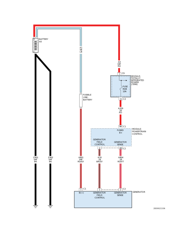
For a complete wiring diagram, refer to the Wiring Information.
When Monitored:
The engine running. The engine speed greater than 1157 RPM.
Set Condition:
The alternator B+ voltage sense circuit voltage reading exceeds the direct Battery B+ sense circuit. The Generator Output terminal is not connected to the Battery B+ post. One trip fault.
Possible Causes
EXCESSIVE RESISTANCE IN THE (A209) BATTERY FEED CIRCUIT
3.
CHECK THE (A209)
BATTERY FEED CIRCUIT FOR EXCESSIVE RESISTANCE
1.
Disconnect the
PCM C1 harness connector.
2.
Inspect the Engine
Control Direct Battery Feed Fuse in the TIPM.
3.
Perform a voltage
drop test on the (A209) Battery Feed circuit from the PCM C1 harness
connector to the TIPM Fuse Panel.
4.
Using a Voltmeter
probe the PCM C1 harness connector with the Negative lead of the Voltmeter
and back probe the (A209) Battery Feed circuit at the TIPM Fuse Panel
with the Positive lead of the Voltmeter.
WARNING:
When the engine is operating, do
not stand in direct line with the fan. Do not put your hands near
the pulleys, belts or fan. Do not wear loose clothing. Failure to
follow these instructions may result in possible serious or fatal
injury.
5.
Start the engine
6.
Monitor the Voltmeter.
Is the
voltage above 0.4 Volt?
Yes
Repair the excessive
resistance in the (A209) Battery Feed circuit between the PCM and
TIPM.
Using the wiring
diagram/schematic as a guide, inspect the wiring and connectors between
the Generator and the Powertrain Control Module (PCM).
2.
Look for any chafed,
pierced, pinched, or partially broken wires.
3.
Look for broken,
bent, pushed out or corroded terminals. Verify that there is good
pin to terminal contact in the Generator and the Powertrain Control
Module connectors.
4.
Perform any Technical
Service Bulletins that may apply.