P258A- ELECTRIC VACUUM PUMP CIRCUIT
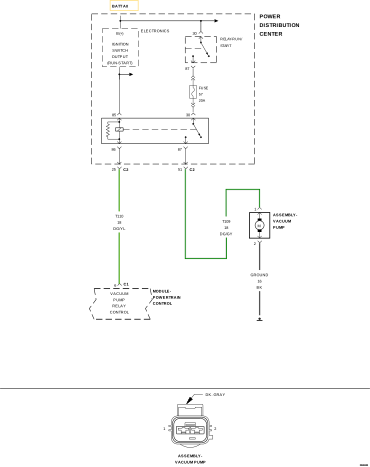 |
For a complete wiring diagram, refer to the Wiring Information.
Theory of Operation
The Electric Vacuum Pump (EVP) system is installed to provide supplemental vacuum to the Brake Booster, when the engine vacuum supply is low. The pump is connected to the engine and the brake booster through a series of hoses and one-way flow check valves. A pressure sensor, mounted in the brake booster, provides information to the ABS/ESP Module. This information is then sent to the Powertrain Control Module (PCM) over the CAN C BUS. The PCM modulates the EVP operation to maintain the brake booster vacuum within a given range. This system ensures that the customer experiences a consistent brake pedal feel under all driving conditions.
-
When Monitored:
With ignition on. Battery voltage above 10.0 Volts.
-
Set Condition:
The actual EVP state is not equal to the desired EVP state. One Trip Fault. Three good trips to turn off the MIL.
Possible Causes |
|---|
| FUSED RUN/ START CIRCUIT OPEN |
| (T110) EVP RELAY CONTROL CIRCUIT OPEN |
| (T110) EVP RELAY CONTROL CIRCUIT SHORTED TO GROUND |
| EVP RELAY |
| POWERTRAIN CONTROL MODULE (PCM) |
Always perform the Pre-Diagnostic Troubleshooting procedure before proceeding. (Refer to 28 - DTC-Based Diagnostics/MODULE, Powertrain Control (PCM) - Standard Procedure).
| 1. | Ignition on, engine not running. |
| 2. | With the scan tool, select View DTCs. |
Is the DTC Active at this time?
Yes
- Go To 2
No
- Perform the INTERMITTENT CONDITION diagnostic procedure. (Refer to 28 - DTC-Based Diagnostics/MODULE, Powertrain Control (PCM) - Standard Procedure).
2. CHECK THE FUSED RUN/ START CIRCUIT
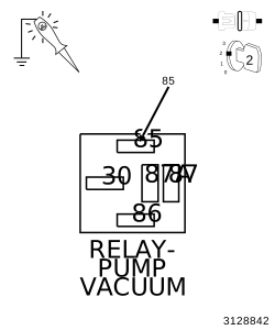 |
| 1. | Turn the ignition off. |
| 2. | Remove the EVP Relay from the relay connector harness. |
| 3. | Ignition on, engine not running. |
| 4. | Using a 12-Volt test light connected to ground, probe the Fused RUN/START circuit (terminal 85) in the EVP Relay harness connector. |
Does the test light illuminate brightly?
Yes
- Go To 3
No
- Repair the open Fused RUN/START circuit.
-
Perform the POWERTRAIN VERIFICATION TEST. (Refer to 28 - DTC-Based Diagnostics/MODULE, Powertrain Control (PCM)
- Standard Procedure).
| 1. | Measure the resistance of the EVP Relay Coil. |
| NOTE: | Measure across terminals 85 and 86 of the relay. |
Is the resistance between 60 to 80 Ohms?
Yes
- Go To 4
No
- Verify that there is good pin to terminal contact in the EVP Relay and Powertrain Control Module connectors. If OK, replace the EVP Relay.
- Perform the POWERTRAIN VERIFICATION TEST. (Refer to 28 - DTC-Based Diagnostics/MODULE, Powertrain Control (PCM) - Standard Procedure).
4. (T110) EVP RELAY CONTROL CIRCUIT OPEN
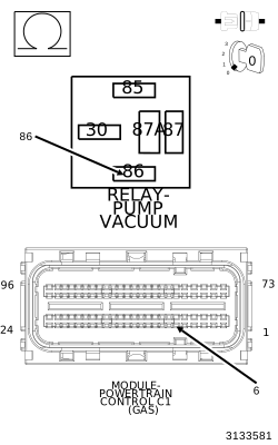 |
| 1. | Disconnect the PCM C1 harness connector. |
| 2. | Measure the resistance of the (T110) EVP relay control circuit from the EVP Relay socket to the PCM C1 harness connector. |
Is the resistance below 5.0 Ohms?
Yes
- Go To 5
No
- Repair the open in the (T110) EVP relay control circuit.
-
Perform the POWERTRAIN VERIFICATION TEST. (Refer to 28 - DTC-Based Diagnostics/MODULE, Powertrain Control (PCM)
- Standard Procedure).
5. (T110) EVP RELAY CONTROL CIRCUIT SHORTED TO GROUND
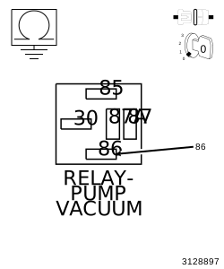 |
| 1. | Measure the resistance between ground and the (T110) EVP Relay control circuit at the EVP Relay socket. |
Is the resistance below 1000 Ohms?
Yes
- Repair the short to ground in the (T110) EVP relay control circuit.
- Perform the POWERTRAIN VERIFICATION TEST. (Refer to 28 - DTC-Based Diagnostics/MODULE, Powertrain Control (PCM) - Standard Procedure).
No
-
Go To 6
6. POWERTRAIN CONTROL MODULE (PCM)
| 1. | Using the wiring diagram/schematic as a guide, inspect the wiring and connectors between the Electric Vacuum Pump, PDC and the Powertrain Control Module (PCM). |
| 2. | Look for any chafed, pierced, pinched or partially broken wires. |
| 3. | Look for broken, bent, pushed out or corroded terminals. |
| 4. | Monitor the scan tool data relative to this circuit and wiggle test the wiring and connectors. |
| 5. | Look for the data to change or for the DTC to reset during the wiggle test. |
| 6. | Perform any Technical Service Bulletins that may apply. |
Were any problems found?
Yes
- Repair as necessary.
- Perform the POWERTRAIN VERIFICATION TEST. (Refer to 28 - DTC-Based Diagnostics/MODULE, Powertrain Control (PCM) - Standard Procedure).
No
- Replace the Powertrain Control Module (PCM) in accordance with the Service Information. (Refer to 08 - Electrical/8E - Electronic Control Modules/MODULE, Powertrain Control - Removal) .
- Perform the POWERTRAIN VERIFICATION TEST. (Refer to 28 - DTC-Based Diagnostics/MODULE, Powertrain Control (PCM) - Standard Procedure).