B2199-16-BATTERY VOLTAGE - CIRCUIT VOLTAGE BELOW THRESHOLD
For a complete wiring diagram, refer to the Wiring Information.
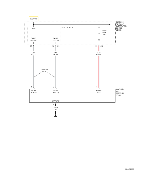 |
For a complete wiring diagram, refer to the Wiring Information.
-
When Monitored:
Continuously.
-
Set Conditions:
Any time the Tire Pressure Monitoring (TPM) Module senses voltage input below 8.0 volts for over 20 ms, this code will set.
| Possible Causes |
| NON-FCC COMPLIANT COMPONENTS |
| LOW VOLTAGE ENGINE DTC |
| (A27) FUSED B(+) CIRCUIT HIGH RESISTANCE |
| (Z905) GROUND CIRCUIT HIGH RESISTANCE |
| TIRE PRESSURE MONITORING (TPM) MODULE |
Diagnostic Test
1. CHECK POWERTRAIN CONTROL MODULE (PCM) DTCs
| NOTE: | Make sure the battery is fully charged before proceeding. |
| 1. | Ignition on, engine not running. |
| 2. | With the scan tool, read PCM DTCs. |
Are there any battery or charging systems DTCs?
Yes
- (Refer to 28 - DTC-Based Diagnostics/MODULE, Powertrain Control (PCM) - Diagnosis and Testing) and perform the appropriate diagnostic procedure.
No
- Go To 2
| 1. | With the scan tool, record and erase stored DTCs. |
| 2. | Start the engine and run for two minutes. |
| 3. | With the scan tool, read DTCs. |
Is the DTC active at this time?
Yes
- Go To 3
No
- Go To 5
3. (A27) FUSED B(+) CIRCUIT OPEN OR HIGH RESISTANCE
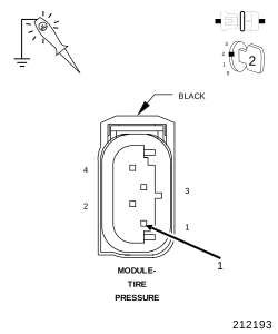 |
| 1. | Turn the ignition off to the lock position |
| 2. | Disconnect the TPM Module harness connector. |
| 3. | Ignition on, engine not running. |
| 4. | Using a 12-volt test light connected to ground, check (A27) Fused B(+) circuit in the TPM Module harness connector. |
| NOTE: | The test light must illuminate brightly. Compare the brightness to that of a direct connection to the battery. |
Does the test light illuminate brightly?
Yes
- Go To 4
No
- Repair the (A27) Fused B(+) circuit for an open or high resistance.
-
Perform the TPM VERIFICATION
TEST. (Refer to 28 - DTC-Based
Diagnostics/MODULE, Tire Pressure (TPM)
- Standard Procedure).
4. (Z905) GROUND CIRCUIT OPEN OR HIGH RESISTANCE
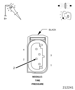 |
| 1. | Turn the ignition off to the lock position |
| 2. | Using a 12-volt test light connected to 12-volts, check the (Z905) Ground circuit in the TPM Module harness connector. |
| NOTE: | The test light must illuminate brightly. Compare the brightness to that of a direct connection to the battery. |
Does the test light illuminate brightly?
Yes
- Replace the Tire Pressure Monitoring (TPM) Module in accordance with Service Information. (Refer to 22 - Tires and Wheels/Tire Pressure Monitoring/MODULE, Tire Pressure Monitoring (TPM) - Removal).
- Perform the TPM VERIFICATION TEST. (Refer to 28 - DTC-Based Diagnostics/MODULE, Tire Pressure (TPM) - Standard Procedure).
No
- Repair the (Z905) Ground circuit for an open or high resistance.
-
Perform the TPM VERIFICATION
TEST. (Refer to 28 - DTC-Based
Diagnostics/MODULE, Tire Pressure (TPM)
- Standard Procedure).
5. INTERMITTENT WIRING AND CONNECTORS
| 1. | Using the wiring diagrams as a guide, check all related splices and connectors for signs of water intrusion, corrosion, pushed out or bent terminals, and correct pin tension. |
| 2. | Wiggle test the wiring harness and connectors while monitoring the scan tool data relative to this circuit. |
| 3. | Look for the data to change or for the DTC to reset during the wiggle test. |
| 4. | While monitoring the scan tool data relative to this circuit. |
| 5. | Look for the data to change other than as expected or for the DTC to reset. |
Were any problems found?
Yes
- Repair as necessary.
- Perform the TPM VERIFICATION TEST. (Refer to 28 - DTC-Based Diagnostics/MODULE, Tire Pressure (TPM) - Standard Procedure).
No