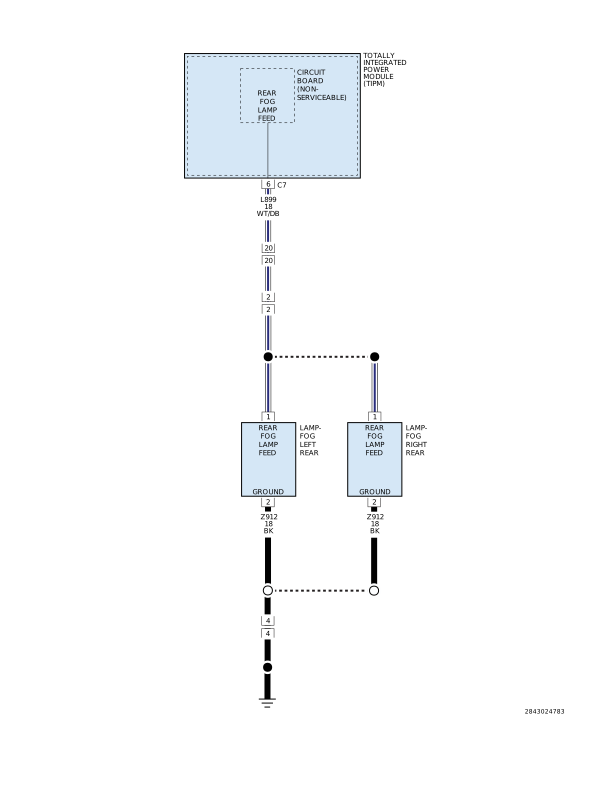
Home › 28 - DTC-Based Diagnostics › MODULE, Totally Integrated Power (TIPM) › B1663-REAR FOG LAMP CONTROL CIRCUIT LOWB1663-REAR FOG LAMP CONTROL CIRCUIT LOW
For a complete wiring diagram, refer to the Wiring Information .
Possible Causes
(L239) REAR FOG LAMP CONTROL CIRCUIT SHORT TO GROUND
LEFT REAR FOG LAMP BULB
RIGHT REAR FOG LAMP BULB
TOTALLY INTEGRATED POWER MODULE
1.
INTERMITTENT CONDITION
2.
With the scan tool, clear all DTCs.
3.
Turn the Rear Fog Lamps on.
4.
With the scan tool, read DTCs.
Does the scan tool display active: B1663-REAR FOG LAMP CONTROL CIRCUIT LOW? Yes
No
(Refer to 28 - DTC-Based Diagnostics/MODULE, Totally Integrated Power (TIPM)
- Standard Procedure) .
2.
LEFT REAR FOG LAMP BULB
1.
Turn the ignition off.
2.
Disconnect the Left Rear Fog Lamp Bulb.
4.
With the scan tool, read DTCs.
Does the DTC reset? Yes
No
3.
RIGHT REAR FOG LAMP BULB
1.
Turn the ignition off.
2.
Disconnect the Right Rear Fog Lamp Bulb.
4.
With the scan tool, read DTCs.
Does the DTC reset? Yes
No
4.
(L239) REAR FOG LAMP CONTROL CIRCUIT SHORT TO GROUND
1.
Turn the ignition off.
2.
Disconnect the TIPM C6 harness connector.
3.
Disconnect the Left and Right Rear Fog Lamp harness connectors.
4.
Measure the resistance between ground and the (L239) Rear Fog Lamp Control circuit.
Is the resistance above 10k Ohms? Yes
No