B1820-HOOD AJAR INPUT CIRCUIT HIGH
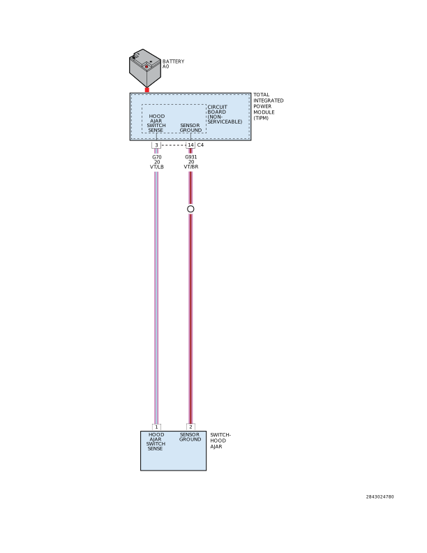
For a complete wiring diagram, refer to the Wiring Information.
 |
-
When Monitored:
Continuously
-
Set Condition:
When the Totally Integrated Power Module senses 12 volts on the Hood Ajar Switch Sense circuit for over 10 seconds, this code will set.
Possible Causes |
|---|
| (G931) SENSOR GROUND CIRCUIT OPEN |
| (G70) HOOD AJAR SWITCH SENSE CIRCUIT SHORT TO VOLTAGE |
| (G70) HOOD AJAR SWITCH SENSE CIRCUIT OPEN |
| HOOD AJAR SWITCH OPEN |
| TOTALLY INTEGRATED POWER MODULE (TIPM) |
1. TEST FOR INTERMITTENT CONDITION
| NOTE: | Open the hood and make sure the Hood Ajar Switch is connected before proceeding |
| 1. | With the scan tool, record and erase DTCs |
| 2. | Close the hood. |
| 3. | Cycle the ignition from on to off. |
| 4. | Turn the ignition on. |
| 5. | Open then close the hood. |
| 6. | With the scan tool, read DTCs. |
Does the scan tool display B1820-HOOD AJAR INPUT CIRCUIT HIGH?
Yes
- Go To 2
No
- The conditions that caused this code to set are not present at this time. Using the wiring diagram/schematic as a guide, inspect the wiring and connectors.
-
Perform the
BODY VERIFICATION TEST. (Refer
to 28 - DTC-Based Diagnostics/MODULE, Totally Integrated Power (TIPM)
- Standard Procedure).
2. INCORRECT HOOD AJAR SWITCH INSTALLED
| 1. | Inspect the retainer ring on the hood ajar switch. |
| 2. | A dark brown retainer ring identifies the hood ajar switch used for certain export applications, while a white retainer ring identifies the remote starter system application. |
Is the correct switch installed?
Yes
- Go To 3
No
- Replace the Hood Ajar Switch.
-
Perform the
BODY VERIFICATION TEST. (Refer
to 28 - DTC-Based Diagnostics/MODULE, Totally Integrated Power (TIPM)
- Standard Procedure).
| 1. | Disconnect the Hood Ajar Switch harness connector. |
| 2. | Depress the plunger of the hood ajar switch and measure the resistance between the two terminals of the switch. |
Is the resistance approximately 1k Ohms?
Yes
- Go To 4
No
- Replace the Hood Ajar Switch.
-
Perform the
BODY VERIFICATION TEST. (Refer
to 28 - DTC-Based Diagnostics/MODULE, Totally Integrated Power (TIPM)
- Standard Procedure).
4. (G931) SENSOR GROUND CIRCUIT OPEN
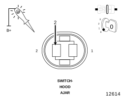 |
| 1. | Using a 12-volt Test Light connected to 12-volts, check the (G931) Sensor Ground circuit. |
Does the test light illuminate?
Yes
- Go To 5
No
- Repair the (G931) Sensor Ground circuit for an open.
-
Perform the
BODY VERIFICATION TEST. (Refer
to 28 - DTC-Based Diagnostics/MODULE, Totally Integrated Power (TIPM)
- Standard Procedure).
5. (G70) HOOD AJAR SWITCH SENSE CIRCUIT SHORT TO VOLTAGE
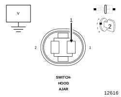 |
| 1. | Disconnect the TIPM C4 connector. |
| 2. | Turn the ignition on. |
| 3. | Measure the voltage between the (G70) Hood Ajar Switch Sense circuit and ground. |
Is there any voltage present?
Yes
- Repair the (G70) Hood Ajar Switch Sense circuit for a short to voltage.
- Perform the BODY VERIFICATION TEST. (Refer to 28 - DTC-Based Diagnostics/MODULE, Totally Integrated Power (TIPM) - Standard Procedure).
No
-
Go To 6
6. (G70) HOOD AJAR SWITCH SENSE CIRCUIT OPEN
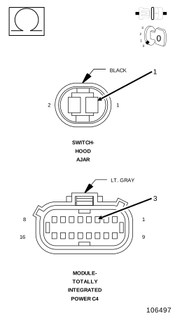 |
| 1. | Turn the ignition off. |
| 2. | Measure the resistance of the (G70) Hood Ajar Switch Sense circuit between the TIPM C4 connector and the Hood Ajar Switch connector. |
Is the resistance below 2.0 Ohms?
Yes
- Replace the Totally Integrated Power Module (TIPM) in accordance with the service information.
- Perform the BODY VERIFICATION TEST. (Refer to 28 - DTC-Based Diagnostics/MODULE, Totally Integrated Power (TIPM) - Standard Procedure).
No
- Repair the (G70) Hood Ajar Switch Sense circuit for an open.
-
Perform the
BODY VERIFICATION TEST. (Refer
to 28 - DTC-Based Diagnostics/MODULE, Totally Integrated Power (TIPM)
- Standard Procedure).