C1404-TRANSFER CASE RANGE POSITION SENSOR CIRCUIT LOW
 |
For a complete wiring diagram, refer to the Wiring Information.
-
When Monitored:
Ignition on with battery voltage between 9.0 Volts and 16.0 Volts.
-
Set Condition:
The Totally Integrated Power Module (TIPM) detects a short to ground on the Transfer Case Position Sensor Signal circuit for 2.0 seconds.
Possible Causes |
|---|
| (T313) MODE SENSOR SIGNAL CIRCUIT SHORTED TO GROUND |
| (T313) MODE SENSOR SIGNAL CIRCUIT SHORTED TO (K91) SENSOR GROUND CIRCUIT |
| TRANSFER CASE (4WD) SWITCH |
| TOTALLY INTEGRATED POWER MODULE (TIPM) |
1. T-CASE POSITION SENSOR VOLTAGE BELOW 0.2 VOLTS
| 1. | Ignition on, engine not running. |
| 2. | With the scan tool under TIPM, read the T-Case Position Sensor voltage. |
Is the voltage below 0.2 of a volt?
Yes
- Go To 2
No
-
Go To 5
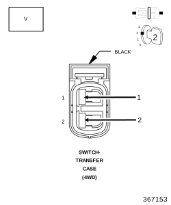
2. (T313) MODE SENSOR SIGNAL CIRCUIT VOLTAGE BELOW 4.9 VOLTS
 |
| 1. | Turn the ignition off to the lock position. |
| 2. | Disconnect the Transfer Case (4WD) Switch harness connector. |
| 3. | Ignition on, engine not running. |
| 4. | Measure the voltage of the (T313) Mode Sensor Signal circuit and the (K91) Sensor Ground at the Transfer Case (4WD) Switch harness connector. |
Is the voltage below 4.9 volts?
Yes
- Go To 3
No
- Replace the Transfer Case (4WD) Switch in accordance with the Service Information.
-
Perform the BODY VERIFICATION TEST.
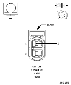
3. (T313) MODE SENSOR SIGNAL CIRCUIT SHORTED TO GROUND
 |
| 1. | Turn the ignition off to the lock position. |
| 2. | Disconnect the TIPM C1 harness connector. |
| 3. | Measure the resistance between ground and the (T313) Mode Sensor Signal circuit at the Transfer Case (4WD) Switch harness connector. |
Is the resistance below 5.0 Ohms?
Yes
- Repair the (T313) Mode Sensor Signal circuit for a short to ground.
- Perform the BODY VERIFICATION TEST.
No
-
Go To 4
4. (T313) MODE SENSOR SIGNAL CIRCUIT SHORTED TO THE (K91) SENSOR GROUND CIRCUIT
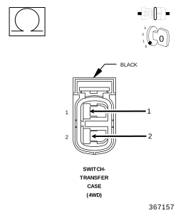 |
| 1. | Measure the resistance between the (T313) Mode Sensor Signal circuit and the (K91) Sensor Ground circuit at the Transfer Case (4WD) Switch harness connector. |
Is the resistance below 5.0 Ohms?
Yes
- Repair the (T313) Mode Sensor Signal circuit for a short to the (K91) Sensor Ground circuit.
- Perform the BODY VERIFICATION TEST.
No
- Replace the Totally Integrated Power Module (TIPM) in accordance with the Service Information.
-
Perform the BODY VERIFICATION TEST.
5. INTERMITTENT WIRING AND CONNECTORS
| 1. | The conditions necessary to set this DTC are not present at this time. |
| 2. | Using the wiring diagram/schematic as a guide, inspect the wiring and connectors. |
| 3. | While monitoring the scan tool data relative to this circuit, wiggle test the wiring and connectors. |
| 4. | Look for the data to change or for the DTC to reset during the wiggle test. |
Were any problems found?
Yes
No