2014 Jeep Wrangler JK Factory Service Manual 28 - DTC-Based Diagnostics

U0001-CAN C BUS CIRCUIT


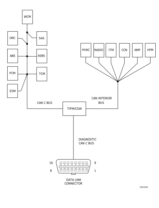
For a complete wiring diagram, refer to the Wiring Information.


Possible Causes

(D65) CAN C BUS (+) CIRCUIT SHORTED TO GROUND
(D64) CAN C BUS (-) CIRCUIT SHORTED TO VOLTAGE
(D65) CAN C BUS (+) CIRCUIT SHORTED TO (D64) CAN C BUS (-) CIRCUIT
ANTILOCK BRAKE MODULE
POWERTRAIN CONTROL MODULE (PCM)
ELECTRIC GEAR SHIFT MODULE (ESM)
TRANSMISSION CONTROL MODULE (TCM)
STEERING ANGLE SENSOR (SAS)
AUTOMATIC SWAY BAR SYSTEM MODULE
WIRELESS CONTROL MODULE (WCM)
OCCUPANT RESTRAINT CONTROLLER (ORC)
TOTALLY INTEGRATED POWER MODULE (TIPM)

1. TEST FOR INTERMITTENT CONDITION


1. Turn the ignition on.
2. Using the scan tool, record and erase TIPM DTCs.
3. Cycle the ignition from on to off three times.
4. Turn the ignition on.
5. Using the scan tool, read active TIPM DTCs.


Does the scan tool display this DTC as active?

Yes


No


2. ANTILOCK BRAKE MODULE - INTERNAL SHORT


1. Turn the ignition off.
2. Disconnect the Antilock Brake Module harness connector.
3. Turn the ignition on.
4. Using the scan tool, record and erase TIPM DTCs.
5. Cycle the ignition from on to off three times.
6. Turn the ignition on.
7. Using the scan tool, read active TIPM DTCs.


Does the scan tool display this DTC as active?

Yes


No


3. POWERTRAIN CONTROL MODULE - INTERNAL SHORT


1. Turn the ignition off.
2. Disconnect the Powertrain Control Module C1 or C2 (Diesel) harness connector.
3. Turn the ignition on.
4. Using the scan tool, record and erase TIPM DTCs.
5. Cycle the ignition from on to off three times.
6. Turn the ignition on.
7. Using the scan tool, read active TIPM DTCs.


Does the scan tool display this DTC as active?

Yes


No


4. TRANSMISSION CONTROL MODULE - INTERNAL SHORT


1. Turn the ignition off.


NOTE: If vehicle is not equipped with this module, answer yes to the question.
2. Disconnect the Transmission Control Module harness connectors.
3. Turn the ignition on.
4. Using the scan tool, record and erase TIPM DTCs.
5. Cycle the ignition from on to off three times.
6. Turn the ignition on.
7. Using the scan tool, read active TIPM DTCs.


Does the scan tool display this DTC as active?

Yes


No


5. STEERING ANGLE SENSOR - INTERNAL SHORT


1. Turn the ignition off.


NOTE: If vehicle is not equipped with this module, answer yes to the question.
2. Disconnect the Steering Angle Sensor harness connector.
3. Turn the ignition on.
4. Using the scan tool, record and erase TIPM DTCs.
5. Cycle the ignition from on to off three times.
6. Turn the ignition on.
7. Using the scan tool, read active TIPM DTCs.


Does the scan tool display this DTC as active?

Yes


No


6. AUTOMATIC SWAY BAR SYSTEM MODULE - INTERNAL SHORT


1. Turn the ignition off.


NOTE: If vehicle is not equipped with this module, answer yes to the question.
2. Disconnect the Automatic Sway Bar System Module harness connector.
3. Turn the ignition on.
4. Using the scan tool, record and erase TIPM DTCs.
5. Cycle the ignition from on to off three times.
6. Turn the ignition on.
7. Using the scan tool, read active TIPM DTCs.


Does the scan tool display this DTC as active?

Yes


No


7. ELECTRIC GEAR SHIFT MODULE - INTERNAL SHORT


1. Turn the ignition off.


NOTE: If vehicle is not equipped with this module, answer yes to the question.
2. Disconnect the Electric Gear Shift Module harness connector.
3. Turn the ignition on.
4. With the scan tool, record and erase TIPM DTCs.
5. Cycle the ignition from on to off three times.
6. Turn the ignition on.
7. With the scan tool, read active TIPM DTCs.


Does the scan tool display this DTC as active?

Yes


No


8. WIRELESS CONTROL MODULE - INTERNAL SHORT


1. Turn the ignition off.
2. Disconnect the Wireless Control Module harness connector.
3. Turn the ignition on.
4. Using the scan tool, record and erase TIPM DTCs.
5. Cycle the ignition from on to off three times.
6. Turn the ignition on.
7. Using the scan tool, read active TIPM DTCs.


Does the scan tool display this DTC as active?

Yes


No


9. OCCUPANT RESTRAINT CONTROLLER - INTERNAL SHORT


1. Turn the ignition off.

WARNING:

Turn the ignition off disconnect the 12-volt battery and wait two minutes before proceeding. Failure to follow these instructions may result in possible serious or fatal injury.

2. Disconnect the Occupant Restraint Controller harness connectors.

WARNING:

Turn the ignition on, then reconnect the 12-volt battery and wait two minutes before proceeding. Failure to follow these instructions may result in possible serious or fatal injury.

3. Using the scan tool, record and erase TIPM DTCs.
4. Cycle the ignition from on to off three times.
5. Turn the ignition on.
6. Using the scan tool, read active TIPM DTCs.


Does the scan tool display this DTC as active?

Yes


No


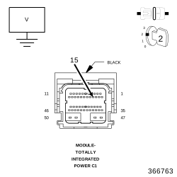
10. CHECK THE (D64) CAN C BUS (-) CIRCUIT FOR A SHORT TO VOLTAGE


1. Measure the voltage between the (D64) CAN C Bus (-) circuit and ground.


Is there any voltage present?

Yes


No


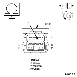
11. CHECK THE (D65) CAN C BUS (+) CIRCUIT FOR A SHORT TO GROUND


1. Turn the ignition off.
2. Measure the resistance between ground and the (D65) CAN C Bus (+) circuit.


Is any resistance present?

Yes


No


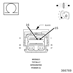
12. CHECK THE (D65) CAN C BUS (+) CIRCUIT FOR A SHORT TO (D64) CAN C BUS (-) CIRCUIT


1. Measure the resistance between the (D65) CAN C Bus (+) circuit and the (D64) CAN C Bus (-) circuit.


Is any resistance present?

Yes


No