U0155-LOST COMMUNICATION WITH CLUSTER/CCN
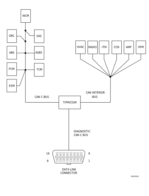 |
For a complete wiring diagram, refer to the Wiring Information.
-
When Monitored:
With the ignition on.
Battery voltage between 10 and 16 volts.
Ignition Off Draw (IOD) fuse installed.
Totally Integrated Power Module (TIPM) is configured correctly.
-
Set Condition:
Bus messages not received from the Cluster/Cabin Compartment Node (CCN) for approximately two to five seconds.
Possible Causes |
|---|
| (D265) CAN INTERIOR BUS (+) (125K) CIRCUIT SHORTED TO VOLTAGE |
| (D264) CAN INTERIOR BUS (-) (125K) CIRCUIT SHORTED TO GROUND |
| DTCS RELATED TO BATTERY VOLTAGE, IGNITION, OR VIN MESSAGES |
| TIPM NOT CONFIGURED CORRECTLY |
| CLUSTER/CCN POWER AND GROUND |
| CLUSTER/CABIN COMPARTMENT NODE (CCN) |
| MODULE THAT SET THE DTC |
1. VERIFY THE DIAGNOSTIC TROUBLE CODE (DTC) IS ACTIVE
| NOTE: | Make sure the IOD fuse is installed and battery voltage is between 10 and 16 volts before proceeding. |
| 1. | With the scan tool, read active DTCs. |
Is this DTC active?
Yes
- Go To 2
No
- (Refer to 29 - Non-DTC Diagnostics/Communication - Diagnosis and Testing) and perform the STORED LOST COMMUNICATION DTCS diagnostic procedure.
2. CHECK FOR ANY OF THE FOLLOWING ACTIVE DTCS
| 1. | With the scan tool, read active DTCs from all modules. |
| NOTE: | Check for TIPM configuration, CAN Interior Bus hardware electrical, VIN Missing/Mismatch, battery or ignition related DTCs. |
Does the scan tool display any active DTCs to the conditions listed above?
Yes
No
- Go To 3
3. VERIFY THE CCN IS ACTIVE ON THE BUS
| 1. | Turn the ignition on. |
| 2. | With the scan tool, select Network Diagnostics. |
| 3. | Verify the CCN is active on the bus. |
Is the CCN active on the bus?
Yes
- Go To 4
No
- (Refer to 29 - Non-DTC Diagnostics/Communication - Diagnosis and Testing) and perform the NO RESPONSE FROM CCN (CLUSTER) diagnostic procedure.
4. CHECK FOR ADDITIONAL COMMUNICATION RELATED DTCS
| 1. | With the scan tool, select Network Diagnostics. |
Is there more than one module with active DTCs “Logged Against” the CCN?
Yes
- Replace/update the Cluster/CCN in accordance with the Service Information.
- Perform the BODY VERIFICATION TEST. (Refer to 28 - DTC-Based Diagnostics/MODULE, Totally Integrated Power (TIPM) - Standard Procedure).
No
- Go To 5
5. CLEAR DTC IN MODULE SETTING FAULT
| 1. | With the scan tool, select the module setting the DTC against the Cluster/CCN. |
| 2. | Clear active DTCs. |
Is this DTC still active?
Yes
- Replace/update the module that set this DTC in accordance with the Service Information.
- Perform the appropriate verification test for the module being replaced. If there is no verification test for the associated module perform the BODY VERIFICATION TEST. (Refer to 28 - DTC-Based Diagnostics/MODULE, Totally Integrated Power (TIPM) - Standard Procedure).
No
- Go To 6
| 1. | Cycle the ignition from RUN to OFF three times ending with the key in the RUN position. |
Does this DTC become active?
Yes
- Go To 7
No
- The condition is not present at this time. Using the wiring diagram/schematic as a guide, inspect the wiring for chafed, pierced, pinched, and partially broken wires and the wiring harness connectors for broken, bent, pushed out, and corroded terminals.
- Perform the BODY VERIFICATION TEST. (Refer to 28 - DTC-Based Diagnostics/MODULE, Totally Integrated Power (TIPM) - Standard Procedure).
7. CHECK FOR ADDITIONAL LOST COMMUNICATION FAULTS
| 1. | With the scan tool, select Network Diagnostics. |
Does the TIPM and other CAN Interior BUS (125K) modules show Lost Communication with the remaining CAN Interior BUS (125K) modules?
Yes
- Go To 8
No
- Replace/update the module that set this DTC in accordance with the Service Information.
- Perform the appropriate verification test for the module being replaced. If there is no verification test for the associated module perform the BODY VERIFICATION TEST. (Refer to 28 - DTC-Based Diagnostics/MODULE, Totally Integrated Power (TIPM) - Standard Procedure).
8. (D265) CAN INTERIOR BUS (+) (125K) CIRCUIT SHORTED TO VOLTAGE
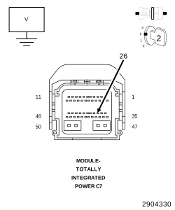 |
| 1. | Measure the voltage between the (D265) CAN Interior Bus (+) (125K) circuit and ground. |
Is the voltage above 5.0 volts?
Yes
- Repair the short to voltage in the (D265) CAN Interior Bus (+) (125K) circuit.
- Perform the BODY VERIFICATION TEST. (Refer to 28 - DTC-Based Diagnostics/MODULE, Totally Integrated Power (TIPM) - Standard Procedure).
No
-
Go To 9
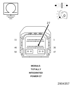
9. (D264) CAN INTERIOR BUS (-) (125K) CIRCUIT SHORTED TO GROUND
 |
| 1. | Turn the ignition off. |
| 2. | Measure the resistance between ground and the (D264) CAN Interior Bus (-) (125K) circuit. |
Is the resistance below 10k Ohms?
Yes
- Repair the short to ground in the (D264) CAN Interior Bus (-) (125K) circuit.
- Perform the BODY VERIFICATION TEST. (Refer to 28 - DTC-Based Diagnostics/MODULE, Totally Integrated Power (TIPM) - Standard Procedure).
No
- Replace/update the module that set this DTC in accordance with the Service Information.
-
Perform the appropriate verification test for the module being replaced. If there is no verification test for the associated module perform the BODY VERIFICATION TEST. (Refer to 28 - DTC-Based Diagnostics/MODULE, Totally Integrated Power (TIPM)
- Standard Procedure).