P0657-SOLENOID SUPPLY VOLTAGE CIRCUIT
For a complete wiring diagram, refer to the Wiring Information.
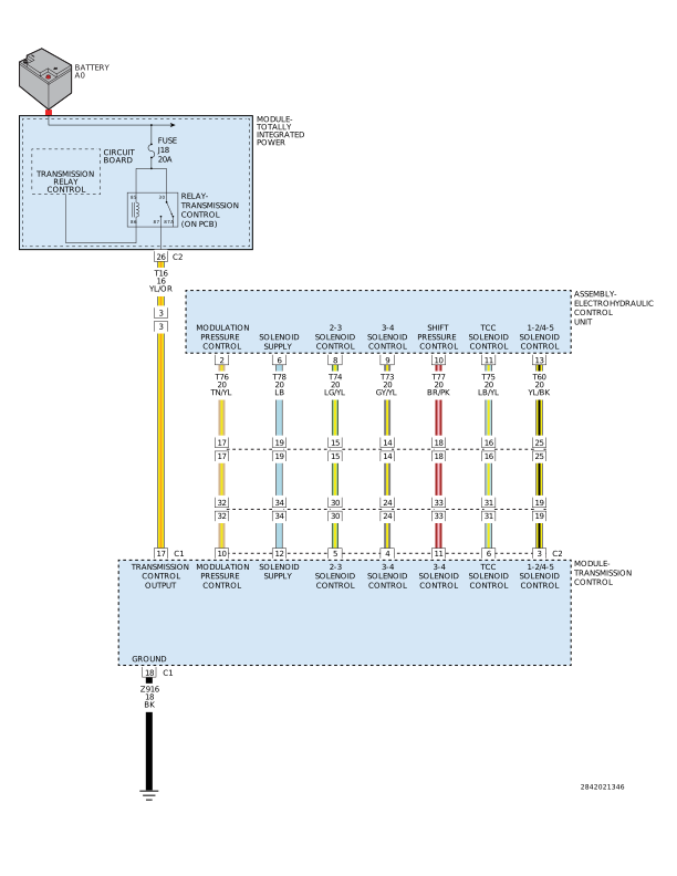 |
Theory of Operation
The Transmission Control Module (TCM) supplies voltage to the TCC solenoid, two pressure solenoids, and three shift solenoids through the Solenoid Supply circuit. The Solenoid Supply circuit high-side driver is turned on during normal operation. If a fault is detected, the driver is turned off to disable the solenoids.
-
When Monitored:
When the output is active and no undervoltage condition exists.
-
Set Condition:
When the monitored supply voltage and battery voltage differ by 3.6 volts.
Possible Causes |
|---|
| (T78) SOLENOID SUPPLY CIRCUIT OPEN |
| (T78) SOLENOID SUPPLY CIRCUIT SHORT TO GROUND |
| (T78) SOLENOID SUPPLY CIRCUIT SHORT TO VOLTAGE |
| TRANSMISSION CONTROL MODULE (TCM) |
Always perform the NAG1 Pre-Diagnostic Troubleshooting procedure before proceeding. (Refer to 28 - DTC-Based Diagnostics/MODULE, Transmission Control (TCM) - Standard Procedure).
1. (T78) SOLENOID SUPPLY CIRCUIT SHORT TO VOLTAGE
| 1. | With the scan tool, check for other transmission DTCs. |
Is the DTC P1629-TCM INTERNAL - SOLENOID SUPPLY/WATCHDOG also present?
Yes
- When both P0657-SOLENOID SUPPLY VOLTAGE CIRCUIT and P1629-TCM INTERNAL - SOLENOID SUPPLY/WATCHDOG DTCs set at the same time is a indication that the (T78) Solenoid Supply Voltage circuit is shorted to voltage. Repair the Solenoid Supply Voltage circuit for a short to voltage. If no short to voltage is present, using the schematics as a guide, check the Transmission Control Module (TCM) terminals for corrosion, damage, or terminal push out. Pay particular attention to all power and ground circuits. If no problems are found replace the TCM in accordance with the Service Information.
- Perform the TRANSMISSION VERIFICATION TEST. (Refer to 28 - DTC-Based Diagnostics/MODULE, Transmission Control (TCM) - Standard Procedure).
No
- Go To 2
2. (T78) SOLENOID SUPPLY CIRCUIT OPEN
| 1. | Turn the ignition off to the lock position. |
| 2. | Disconnect the TCM C2 harness connector. |
| 3. | Disconnect the Electrohydraulic Control Unit Assembly harness connector. |
| 4. | Measure the resistance of the (T78) Solenoid Supply Voltage circuit between the TCM C2 harness connector and the Electrohydraulic Control Unit Assembly harness connector. |
Is the resistance above 5.0 Ohms?
Yes
- Repair the (T78) Solenoid Supply Voltage circuit for an open.
- Perform the TRANSMISSION VERIFICATION TEST. (Refer to 28 - DTC-Based Diagnostics/MODULE, Transmission Control (TCM) - Standard Procedure).
No
-
Go To 3
3. (T78) SOLENOID SUPPLY CIRCUIT SHORT TO GROUND
| 1. | Measure the resistance between ground and the (T78) Solenoid Supply circuit. |
Is the resistance below 5.0 Ohms?
Yes
- Repair the (T78) Solenoid Supply circuit for a short to ground.
- Perform the TRANSMISSION VERIFICATION TEST. (Refer to 28 - DTC-Based Diagnostics/MODULE, Transmission Control (TCM) - Standard Procedure).
No
-
Go To 4
4. (T78) SOLENOID SUPPLY CIRCUIT SHORT TO ANOTHER CIRCUIT
| 1. | Measure the resistance between the (T78) Solenoid Supply circuit and all other circuits in the Electrohydraulic Control Unit Assembly harness connector. |
Is the resistance below 5.0 Ohms between the (T78) Solenoid Supply circuit and any other circuit(s) in the Electrohydraulic Control Unit Assembly harness connector?
Yes
- Repair the (T78) Solenoid Supply circuit for a short to another circuit(s).
- Perform the TRANSMISSION VERIFICATION TEST. (Refer to 28 - DTC-Based Diagnostics/MODULE, Transmission Control (TCM) - Standard Procedure)
No
- Using the schematics as a guide, check the Transmission Control Module (TCM) terminals for corrosion, damage, or terminal push out. Pay particular attention to all power and ground circuits. If no problems are found, replace the TCM in accordance with the Service Information.
-
Perform the TRANSMISSION
VERIFICATION TEST. (Refer to
28 - DTC-Based Diagnostics/MODULE, Transmission Control (TCM)
- Standard
Procedure).